Last Updated on Wednesday, December 15, 2004 at 10:57:48. by Nazim Khan.
| PMT | |
| Total Number: | 20 |
| Model: | Hamamatsu R2083 |
| Max voltage | 3500 V |
| Radiator | |
| Dimensions: | dia:6cm; length:5cm |
| Material: | |
| Detector | |
| Intrinisic Timing Resolution | 60 ps |
A. Operating The Time Zero High Voltage Supply
IMPORTANT: The T0 tubes are rated for 3500V maximum. DO NOT EVER EXCEED THIS VOLTAGE. We recommend that the HV is kept well below 3500V at all times.
The T0s are routed to the LECroy Mainframe that is controlled by the HV Controls vi on Plasmon. The tubes are connected to slots ( boards) 17 and 18 and are on channel 0-9 on those boards. Read the HV Manual to know how to control the voltages.
B. Controlling the T0 Discriminators (use the "Plastic" computer)
As of June/19/2001, the discriminator threshold is -200 mV on all T0 channels.
Look at the Plastic HV And Camac Control computer. Make sure you are looking at the intended CAMAC crate (there are two CAMAC crates.) There are two buttons at the top of the VI labelled Display Positive Crate and Display Negative Crate. Make sure you are viewing the correct crate by pressing either of these buttons and by looking at the indicator to the left of the buttons.
The T0 discriminators are located in the tunnel in the trigger camac crates, next to the Cherenkov arrays. They are controlled through the trigger controls on the CAMAC Slow Controls VI (on the Plastic computer). Look at the bottom left side of the CAMAC Controls VI, there is a grey box labelled Time Zero Discriminators. The threshold of all channels on the module can be changed on the screen. Then press the green Write Trigger button (located at upper-left part of the VI).
The channels can be masked as well. The buttons labelled "mask channel" shows yellow for an unmasked channel and black for a masked channel. Toggle the desired button and press the Write Trigger button to change the mask settings for the discriminator.
Note: after you press the green Write Triggers button (upper-left, near the top of the screen), the crate will be written, and then read back by the VI. This takes quite a while. Be patient. The visual indication is, that the button labeled "Press To Read Out All Crates" (down in the middle of the screen) changes to "Reading" and appears depressed. Be patient and wait till it pops up again (about 1 minute).
A. Checking T0 High Voltage:
The T0s are connected to the 2nd LeCroy HV Mainframe in the electronics room. On the HV controls vi on Plasmon, Slots 17 and 18 and channels 0-9 on those slots in the status grid located in the bottom right hand corner of the vi illustrate the status of the T0 tubes. The indicators should be green if the detectors are On and working properly. If they are off, then the indicators should be black. If they are any other color, the channel and state need to be recorded in the logbook, and a T0 expert needs to be called.
B. Verifying that all T0 channels are in the data:
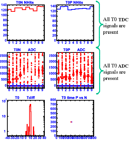
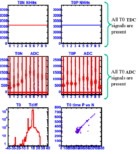
Go to PHONL1 and look at the trigger display. Click on Reset. In the middle of the screen you will find T0N (left) & T0P (right). Click on either T0N or T0P. A canvas labeled "T0 expert plots" will pop up. On that canvas you will see 3 pairs of plots. Look at the top most pair: "T0N/P NHits" and verify that all 10 signals for T0N & T0P are there. For a picture of what this should look like immediately after the reset see HERE, and for what it should look like after it has been running for several minutes see HERE.
If any channels are missing, make a note in the logbook and call any on site T0/TOF/trigger expert.
Please send all comments and suggestions regarding this page to Frank Wolfs. |