Last Updated on Wednesday, December 15, 2004 at 10:56:20. by Author: Erik Johnson
| Scintillator | |
| Total Number: | 240 |
| Dimensions: | 20cm x 8mm x 8mm |
| Material: | Bicron BC404 |
| Speed of light: | |
| Parallel transmission: | 1.9x10⁸m/s |
| Scattered transmission: | 1.5x10⁸m/s |
| Moderate attenuation length: | 1.6m |
| Measured attenuation length: | >30cm |
| Decay constant: | 1.8ns |
| l of max. emission: | 408nm |
| Light Guide | |
| Material: | Acrylic |
| PMT | |
| Model: | Hamamatsu R5900-M4 |
| Minimum effective area: | 18mm x 18mm |
| Number of dynode stages: | 12 |
| Anode geometry: | 2x2 |
| Maximum supply voltage: | +900V |
| Maximum current: | +400 mAmps |
| Responds to a l range of: | 300 to 650nm |
| l of maximum response | 420nm |
| Voltage set for a gain of: | 2.5x10⁶ |
| Detector | |
| Maximum cross-talk: | 10% |
| Position resolution: | 1cm |
| Average timing resolution | 80ps |
| (from a Sr-90 source) | |
| Geometry (Approx.) | |
| Degrees in q | |
| Inner wall: | 90o to 55o |
| Outer wall: | 55o to 32.5o |
| Surface area facing IP per slat: | |
| Active area: | 20cm x 8mm |
| Inactive area: | 20cm x 1mm (1mm gap between scintillators) |
| Total wall segment length: | 1080mm |
| Distance from IP | |
| Inner wall at 90o | 1.7m |
| Out wall at 55o | 2.6m |
| Degrees in f | |
| Inner wall | 7o |
| Outer wall | 4o |
| Percentage of solid angle | 1.42% |
| Total pseudo rapidity range: | 0 to 1.25 |
A. High voltage to tube
1. The high voltage is controlled using the high voltage control VI on the Plastic HV & Camac Controls computer. (The operator's manual is on the desktop with a help button on the VI front panel.)
2. High voltage to the mainframe should always be on.
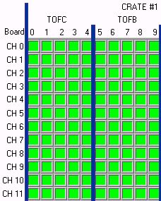
3. All TOF channels need to be enabled, showing green in the status field.
4. If any channels are disabled, determine why by looking at the status field and make a note in the logbook.
5. If an alarm occurs, call TOF expert. Also, inform Edmundo, and note the alarm in the logbook.
6. Turn off the alarm by clicking the alarm button.
7. Refer to the expert's manual for any common solutions.
B. Camac controls
1. The Camac crates are controlled using the Camac controls VI on the Plastic HV & Camac Controls computer. (The operator's manual is on the desktop with a help button on the VI front panel.)
2. All TOF channels should be unmasked, illustrated as a light yellow in the mask fields.
3. If a channel is masked, determine why.
4. Don't unmask a channel for no reason. Just make a note in the logbook.
5. The TOF thresholds should be greater than 9mV (baseline value), and the widths need to be larger than 0ns (baseline value). The widths as seen on the vi front panel are in DAC counts. If the value is at 0, the channel isn't set right, inform the TOF expert.
6. If a communication error occurs while trying to talk to the crates, click the alarm button.
7. Make a note in the logbook.
8. Press the readout all crates button.
9. If the values are reasonable (i.e. other than 9mV for the TOF thresholds and 0 for the widths), then the problem is fixed.
10. If the values turn out to be unreasonable and/or and another error alarm occurs after the read out button is pressed, then call the TOF expert. Also, inform the trigger expert, and note the alarm in the logbook.
11. Refer to the expert's manual for any common solutions.
C. Common running mode settings
These settings are subject to change.
| Electronic Unit | Normal Physics | Cosmic | LED gain monitor | Test/Time Cal. |
| Timing Disc. | ||||
| Threshold | see table | see table | see table | see table |
| Width | see table | see table | see table | see table |
| Trigger Disc. | ||||
| Threshold | see table | see table | see table | see table |
| Width | see table | see table | see table | see table |
| HV settings | ||||
| HV On | Yes | Yes | Yes | N/A |
| Enabled | Yes | Yes | Yes | N/A |
| 4- fold Logic Unit | ||||
| Unmask A | No | Yes | No | No |
| Unmask B | No | Yes | No | No |
| Unmask C | No | No | Yes | No |
| Unmask D | Yes | No | No | Yes |
| Mask A | Yes | No | Yes | Yes |
| Mask B | Yes | No | Yes | Yes |
| Mask C | Yes | Yes | No | Yes |
| Mask D | No | Yes | Yes | No |
| Coinc. Level | 1 | 1 | 1 | 1 |
| Cabled to trig logic | No | Yes | Yes | Yes |
| Time Cal. On | Yes | No | No | Yes |
| Gate Gen. Pulse On for Time Cal | Yes | No | No | No |
| Gate Gen. Pulse On for LED | No | No | Yes | No |
| LED Volts On | No | No | Yes | No |
| LED Voltage | N/A | N/A | 120V | N/A |
| Run Statistics | ||||
| Approx. run time | N/A | 20 minutes | 5 minutes | 5 minutes |
| Number of Events | N/A | 100,000 | 10,000 | 10,000 |
| Frequency of Run | N/A | 1 per week | 1 per week | 1 per month |
D. Location and operations of electronic units
1. Timing Discriminators- these discriminators are located in the TOF Camac crates #3 and #4 in slots 1-15, and slot #17 in crate #3. The Camac controls VI allows control of the discriminator thresholds and widths.
2. Trigger Discriminators- These discriminators are located in slots #20 in TOF crates #3 and #4. The Camac controls VI allows control of the discriminator thresholds and widths.
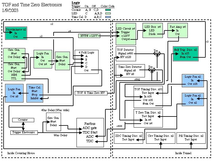
3. 4-fold Logic Unit- The unit is located in the NIM bin above the Fastbus crate. It says 4-fold logic unit on it. There are small pins on the right side of the unit. To mask a channel, stick a pin in the corresponding channel. To set the coincidence level, stick a pin in the corresponding level. Level 1 will generate a NIM pulse is any of the unmasked channels receives a signal. Level 2 requires at least 2 channels to receive a pulse. Level 3 requires 3, and level 4 requires all 4. One cable from the output should be routed to a counter to the left of the unit, and another cable needs to be routed to the trigger electronics expect during normal operation.
The rate in the counter should be approximately 100 counts per second for all runs except during normal running or if the threshold levels for the discriminators are set differently as what is mentioned above.
4. Time Calibrator- The unit is in the NIM bin above the Fastbus crate and is label Time Calibrator. The timing calibration unit has two controls to it. You can choose a range of time over which you want to generate pulses. The period is the time between pulses. With this in mind, the range must be greater than the period. As an example, if the range is 10 microseconds and the period is 2 microseconds, then pulses will be generated at a relative zero, two microseconds after the zero, four microseconds after the zero, six, eight, and ten microseconds after the zero. The rate at which these pulses will fire is controlled using the rate knob at the bottom left of the module.
The start signal should be routed into the 4-fold logic unit, and the stop goes into a fan out. From the fan out, there are two signals that go into the tunnel and trigger the test input of the discriminators.
5. Gate Generator Pulse Unit for Time Calibrator- This unit is located in the TOF NIM bin. It is set up to generate a veto for the Time calibrator such that the calibrator only fires at rate of 1-2Hz.
6. Gate Generator Pulse Unit For LED - This unit is located in the NIM bin above the Fastbus crate and is a dual gate/delay generator NIM module. It is used for the LED gain monitoring system. The delay output of one gate generator is sent into the start of another, and the delay output of the later is sent into the start of the former. This loop generates standard NIM pulses, which can be varied in time by changing the width (delay) of the output signal. The loop is begun by pressing the trigger button on the gate generator. One of the gate generators puts out a NIM signal that is feed into a fan out. Four channels go into the tunnel to drive an LED circuit, while another goes into a gate generator to be properly delayed.
7. LED Voltage Supply Unit- The units are two dual high voltage supplies located above the LeCroy high voltage mainframe. Each module controls the supply voltage to the LED circuit that is in a NIM bin in the tunnel. There is a dial to control the amount of voltage with a switch to enable the channel. There is a main power switch for each sub-unit in the modules. The display read out can either show current or voltage by using the appropriate switch. The LED circuits require +120V. DO NOT exceed this voltage. Damage to the LED system and/or the photo-tubes may occur.
A. Checking High Voltage to TOF.
This is HV ON.
This is HV OFF.
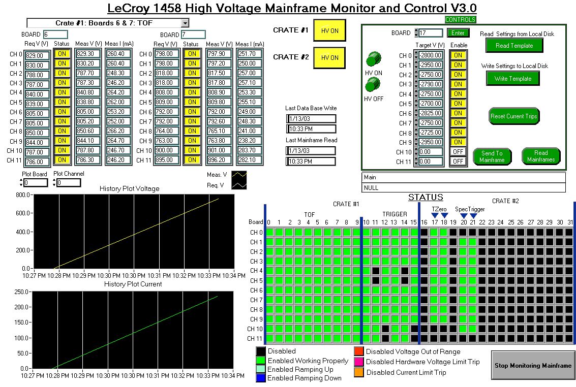
Checking the High Voltage Actual State- Go to the Plastic HV & Camac Controls Computer. Make sure you are looking at the HV controls VI, titled LeCroy 1458 High Voltage Mainframe Monitor and Control and looks similar to this.
Look at the Status fields and remember what boards 0-9 look like to compare them to the Nominal State.
Actions- If any of the TOF channels are off, call a TOF expert.
B. Checking TOF Discriminators
Finding the Camac Controls VI- The TOF Camac Controls VI is located on the Plastic HV and Camac Controls Computer. Make sure you are looking at the VI that is titled GPIB Camac Control for TOF and Trigger Discriminators.
Checking X and Q- The values of X and Q are printed on the upper right hand side of the VI front panel.
Action on X and Q Check- If X or Q are invalid, press the Read Out All Crates button. Recheck. If still invalid, stop the VI by pressing the Press to End Program button. Restart the VI by double clicking the Camac Controls icon on the desktop and pressing the start arrow in the left hand corner of the menu bar.
C. Checking Termination of input to ADC GATE
Finding the TOF CAT unit- The CAT unit is located in slot #3 in the FASTBUS crate in Rack#4 in the electronics room. Slot #3 is to the far right in the crate.
Checking the ADC gate inputs - The ADC gate inputs are located about a third of the way down the CAT unit. There are 2 inputs to the ADC gate: one connected to the trigger electronics via a single twisted pair cable and the other input needs to be terminated
Action on ADC inputs - If the second input is not terminated, then terminate it with a 50 ohm terminator. Make an entry to the log book and contact a TOF representative.
Checking the TOF UPS's- The TOF UPS's are located in the rack on the negative x side of the magnet. They are sticking out from the rack. Look on the front of each of the UPS's. Their are a number of LEDs that should be illuminated. If these are off, the UPS is off. The UPS should never be off. Note why the UPS is off, and do every thing necessary to turn the UPS on. Contact TOF expert if necessary.
Checking if the Camac Crate Is On- If either crate is on, there should be fans blowing which cool the crate. The crate outside the magnet will have a red square led lite in the upper right hand corner if the crate is on. The crate under the magnet has a switch which should be switched on. Now, a crate may trip becasue it is broken. There are digital read outs on both crates. The crate outside of the maget has a display that the user can scroll through using the button to the left of hte display. This display window is to the left of the power switch. On the crate inside the maget, it also has a display. To read out the voltages and currents from the crate, there are a series of buttons by the display which when pressed will tell the crate to display the measured current or the measured voltage on any one of the lines. If there is a fault, the display will tell you on either crate. Furthermore, if the fans are off, the crate is in a fault mode. Furthermore, if the camac controls vi gives a warning, the crate is off. Write any fault down, and toggle to power to the crate. The camac controls vi needs to be restarted as well. Don't touch the crate if you don't feel confortable with trying to fix the problem. In any case, contract the TOF expert if there is any fault.
Checking the Remote Mode for the Discriminators- The discriminators should be in remote mode which is indicated by a red LED. The LED is located at the top of each of the Discriminator modules. There are 17 modules in the Camac crate under the magnet and 16 modules in the Camac crate on the cart. If any of the LED's are off, then restart the Camac Controls VI. If this doesn't fix the problem, then contact the TOF expert.
E. Doing the Diagnostic Run Mode Checks
Checking the TOF 4-fold Logic Trigger Unit- This unit is located in the TOF NIM BIN which is above the Fastbus crate. The 4-fold logic unit is labeled as a 4-fold logic unit. The unit is split into two modules. The top module on the unit has the various TOF self-triggers run through it. There are small holes which are labeled A, B, C, and D to the right of the inputs. A, B, and C should have a pin in them. D is for the time calibrator. This channel need to be enabled to make sure that the time reference signal triggers the DAQ.
Checking the LED HV- the LED HV units are located just about the LeCroy High Voltage mainframe. They are two dual high voltage units. Each channel on the units provides voltage to the LED circuits. The high voltage should be OFF when there isn't an LED run commencing. If there isn't an LED run commencing and they are on, dial down the voltage by turning the large dial on the unit counter clock-wise and turn them off by switching the on/off switch to off..
Checking the Time Calibrator- The Time calibrator is located in the TOF NIM bin, which is located above the Fastbus crate. The time calibrator is labeled as Time Calibrator. This unit needs to run all the time, except when conducting another calibration run. If the unit is off, it must be turned on.
Checking the Time Calibration Enabler- The Time Calibrator is enabled/ disbaled via a gate/delay genator located to the right of the Time Calibrator. The bottom LED should pulse at approximately 1Hz, as should the LED on the Time calibrator. The gate/delay generator should be set to 10s Width on the top and 100ms width on the bottom.
Checking the Time Calibration Enable Cable- The enable signal for the Time Calibrator is set to the back of the unit and comes from the gate/delay generator to the right of the unit. A cable clearly labeled as TC Inhibitor shoudl be plugged into the TTL output of the bottom section of the gate/delay generator.
F. What to do if there is an (old) statement beside ToF & Trigger Voltages.
When this occurs, the information gathereed by the high voltage vi for the plastic detectors isn't being written to the database. The most likely reason why this is occuring is that the vi is in a funny state. Follow these intructions:
- On the HV controls vi, click the Read Mainframe button.
- Wait until the vi finishes reading, then refresh the portal webpage.
- If the (old) statement is still there, or if the Read Mainframe button did nothing, hit the stop button on the vi. This button is located in the upper left hand corner of the vi in the run control toolbar. It looks like a stop sign.
- Close the vi window.
- Open the vi by double clicking the HV Control v3.1 shortcut on the desktop.
- Maximize the window and start the vi by clicking on the white arrow in the upper right hand corner on the run control toolbar.
- Wait until the vi finishes loading in all the ramp and trip values and reads all the values from the mainframe.
- Once the vi is in an operable state, the (old) statement show disappear after the database is updated. If the (old) statement doesn't disappear then call a TOF expert.
Please send all comments and suggestions regarding this page to Frank Wolfs. |