Last Updated on Thursday, October 16, 2003 at 12:46:02 . by Author: Nazim Khan
Expert’s Guide to the TOF.
VIII. Trouble Shooter
This section is designed for constant additions as problems develop and are solved. If any original problem occurs, it should be noted in this section for future reference.
A. Camac controls VI constantly gives an error alarm and all settings are at baseline
There are 2 known possibilities for this problem as follows:
i. The vi is in a funny state OR
ii. The power to the crates can be off.
To determine which of the 2 is the problem you must "Read out all crates." This action will quickly tell you if the vi is functioning properly. If the vi is functioning properly it will return valid X and Q. If valid X and Q are returned after reading out all the crates then the alarm was an anomaly, and there is no need to do anything else. If the vi is not functioning properly (i.e. X and Q are not valid) then you must restart it as follows:
1. Exit Labview by going to the File menu and selecting Exit. This will close all Labview windows. (You will have to restart the other vis also)
2. Restart Labview by clicking on the desktop icon for "CAMAC CONTROLS"
3. Once the vi is opened, click on the start/execute button located on the top left hand corner of the vi window. You should then see a black arrow - this means that the vi is running.
If the error continues and you see that only baseline values appear (9mV & 0ns) then the crate(s) may be off. To check if the crate(s) is/are off check the UPS on the Portal. If the UPS connected to wall TB has no load then that crate is off. Since the UPS connected to the TC wall also has other devices connected to it the load will not read zero for that UPS (it will be much lower than the usual 44, probably at about 10). In this case the crate(s) must be turned back on when there is access to the tunnel. NOTE: The Upper TOF UPS as labeled in the Portal is actually physically the lower one in the tunnel and is connected to wall TB.
There is now a 3rd known possibility for this problem as follows:
iii. Either a discriminator module or CAMAC slot may be broken
If this is the case then the procedures above will fail and it will require prolonged tunnel access to further debug the problem. To determine whether this is the problem you will need to unseat each module in the crate with the power OFF and then reseat each one at a time and checking to see if communication with that particular unit is reestablished. Repeat this procedure for each module. If you detect a bad channel or discriminator then replace the discr. or use another slot. If not then the CAMAC crate may need to be replaced.
Useful Debugging tools
On Plasmon in E: Slow Controls/Camac Control/ there are 2 vis called readgen.vi and writegen.vi. These 2 vis are simple and can set the discriminators to remote/local modes as well as test its mode. If "Help" is activated from the drop down menus the various parameters needed to input into the vis will be displayed as you move the cursor over each entry box. The important parameters are as follows:
GPIB Address : 3 (for TC), 4 (for TB)
GPIB bus :2 (for TOF)
F: 24 (set N to local mode) N is the slot # of the particular discriminator
F: 26 (set N to remote mode) N is the slot # of the particular discriminator
F: 27 (test status of N) N is the slot # of the particular discriminator
These F commands set only 1 discriminator to local/remote mode at a time. When you execute F=24 and it is successful X&Q will turn red and then F=27 then only X will remain red. If both remain red then something is wrong.
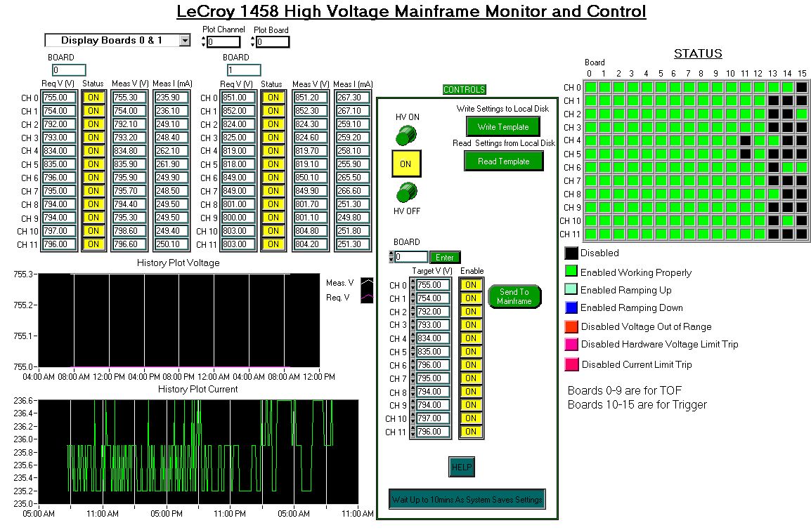
B. Error Message on HV (on Plastic HV & CAMAC CONTROLS)
There are 7 possible modes displayed on the HV status monitor, but only 3 are error messages.
I. If "Disabled Voltage Out of Range" is the error then check the following:
1. Note which channel(s) and board(s) are giving the error.
2. Locate the requested voltage and measured voltage by using the drop down menu on the top left hand corner of the "LeCroy 1458 High Voltage
Mainframe Monitor and Control" window.3. Look at the voltage history of the channel and board which is giving the error by entering the relevant numbers in the boxes provided in the top left corner of the screen.
4. If there has been any large fluctuations (+/- 5V) over the previous 24 hours check the log book for any mention of this and make a note in the log book.
5. If the required and measured voltages are within 5V of each other then you must turn off the HV to that channel and then turn it back on. You do this as follows:
a) First set the channel's Control to "OFF" then click the "SEND TO MAINFRAME" button. This action will take a few minutes to complete and the button will say "SENDING...."
b) Once this is done you must then enable the same channel by changing the "OFF" to "ON" and clicking on the "SEND TO MAINFRAME" once again. NOTE: Make sure you are on the correct board corresponding to the red square in question.
This should reset the error and the square should turn green and stay green.
6. If the requested voltage and measured voltages are NOT within 5V of each other then follow #5 above If it stays green then all is ok, but if the errors occurs immediately again then disable the channel. There may be something wrong with the mainframe such as loose cables. The problem must then be more thoroughly investigated.
NOTE: The most common reason why this alarm occurs is that a channels requested voltage is zero but is enabled. If the requested voltage is at zero, the channel should be disabled.
II. If "Disabled Hardware Voltage Limit Trip" is the error then check the following:
1. Note which channel(s) and board(s) are giving the error.
2. Locate the requested voltage and measured voltage by using the drop down menu on the top left hand corner of the "LeCroy 1458 High Voltage
Mainframe Monitor and Control" window.3. Look at the voltage history of the channel and board which is giving the error by entering the relevant numbers in the boxes provided in the top left corner of the screen.
4. This trip occurs when the measured voltage is greater than the limit value (+900V), which usually occurs when the requested voltage is set too high. The correct requested voltage must be reset. (if the requested voltage is at zero, the channel should be disabled). You must find the correct requested voltage for this channel in the "green folder" or click on the "TOF & Trigger Voltages" (new page is entitled LHCV status) in the Counting House portal under Detector Status and then set the voltage to that requested value as follows:
a) First set the channel's Control to "OFF" then click the "SEND TO MAINFRAME" button. This action will take a few minutes to complete and the button will say "SENDING ...."
b) Type in the correct value of the voltage in the space provided.
c) Once this is done you must then enable the same channel by changing the "OFF" to "ON" and clicking on the "SEND TO MAINFRAME" once again. NOTE: Make sure you are on the correct board corresponding to the red square in question.
III. If "Disabled Current Limit Trip" is the error then check the following:
1. Note which channel(s) and board(s) are giving the error.
2. Enter the number of the board in the space provided in the CONTROLS panel in the middle of the screen and click on enter.
3. Verify that the tripped channel's control is reading OFF. If it is not click the button so that it shows OFF.
4. Locate the requested voltage and measured voltage by using the drop down menu on the top left hand corner of the "LeCroy 1458 High Voltage
Mainframe Monitor and Control" window.5. Look at the voltage history of the channel and board which is giving the error by entering the relevant numbers in the boxes provided in the top left corner of the screen.
6. This trip usually occurs because of beam blast or radiation blast. Reset the tripped channel(s) as follows:
a) First set the channel's Control to "OFF" then click the "SEND TO MAINFRAME" button. This action will take a few minutes to complete and the button will say "SENDING ...."
b) Once this is done and the "SEND TO MAINFRAME" message returns, you must then enable the same channel by changing the "OFF" to "ON" and clicking on the "SEND TO MAINFRAME" once again. NOTE: Make sure you are on the correct board corresponding to the red square in question.
This should reset the error and the square should turn green and stay green.
7. Change the DV status to 1 for the sequence during which the trip occurred. Enter a note for the reason why the DV status was changed and make sure to include which board and channel tripped and what the error was. (You can tell what the error was by looking at the color that the square turned and checking it with the legend below the green status grid on the HV monitor vi.)
6. Make a note in the log book, making sure to include the board and channel tripped.
C. If you see dips in the energy and/or time efficiency spectra, as shown below, do the following checks:
1. Determine which sensors have the problem by looking at the histos created by the TOFDV macro. If the dip occurs in the energy efficiency spectra (as shown say in the "hOKEeffTB" histogram) then look at the correlation with time to determine if the problem is in the "Up' or "Down" section (i.e. look at the histos of the form "hOKETUTB").
2. Look at the "hOKTUorDTB" and "hOKTUandBTB" histos. if there are corresponding dips and spikes at the same sensor numbers then the cables for those sensors are reversed.
3. Once sensor# is determined find corresponding FB slot and channel number (See green folder).
4. Either physically switch those cables or switch them in the FB map.
D. If you see missing channels, as shown below, do the following checks:
1. Note which channel(s) and board(s) are giving the error.
2. Look at the voltage history of the channel and board which is giving the error by entering the relevant numbers in the boxes provided in the top left corner of the screen and determine which tube(s) has the problem.
3. Look at the tube(s) history.
4. Look at the raw signal at the Patch panel in the counting house. Use ECL-NIM converter for ribbon cables.
5. Look at the signal w.r.t. the ADC gate and/or TDC gate. (For TDC checks, NOTE that the converter Delays stop by ~5ns.)