HV v3.0 Controls Manual
Section I. Starting the VI.
- Check to see if the HV mainframe is on and is set to remote mode.
- Locate the icon on the shift user’s desktop called HV Control v3.0.
- Open the VI by double clicking the icon.
- Maximize the window and make sure all the visible elements are viewable on the monitor.
- Locate the white arrow in the upper left hand corner of the VI.
- Click the arrow to start the VI. The arrow should turn black when the VI is running.
- The VI will initialize the mainframe and load various parameters (ramp up and ramp down rates and trip currents) into the mainframes. Wait ~5minutes.
- A blue indicator stating “Retrieving Data from the Mainframes” will show up. The VI is now getting all the information for each channel from both mainframes. Wait ~5minutes.
- The blue indicator should disappear and the VI is ready to be used.
Section II.
Monitoring the High Voltage Channels.
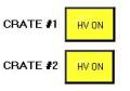
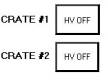
- Checking to see if the high voltage is on or off.
- HV On
- HV Off
- Reading Current Channel Settings.
1. Locate the pull down menu in the upper left hand corner of the VI.
2. Mainframe #1 holds boards 0-15 and Mainframe #2 holds boards 16-31.
3. Choose the board that you want to monitor from the pull down menu.
4. The properties of the all the channels on that board will show up in the fields provided.
a. Req V = requested voltage (V)
b. Status = on implies the channel is enabled; off implies that the channel is disabled.
c. Meas V = measured voltage (V)
d. Meas I = measured current (mA)
- Reading
the History for a Specific Channel
1. Locate the History Plot on the Lower Left hand side of the VI front panel.
2. Type in the desired board number and channel number you wish to display.
3.
 The
history is plotted in the two plots.
The upper plot displays the requested voltage and measured voltage over
a period of time indicated on the x-axis.
The lower plot displays the current over the same period of time.
The
history is plotted in the two plots.
The upper plot displays the requested voltage and measured voltage over
a period of time indicated on the x-axis.
The lower plot displays the current over the same period of time.
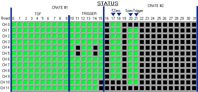
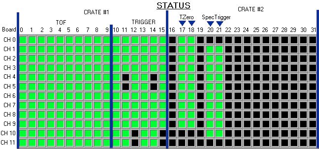
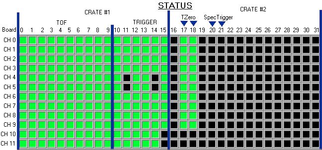
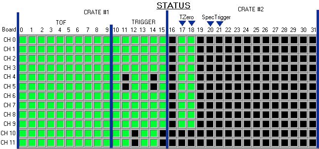
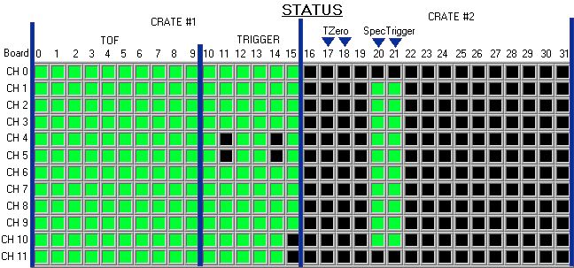
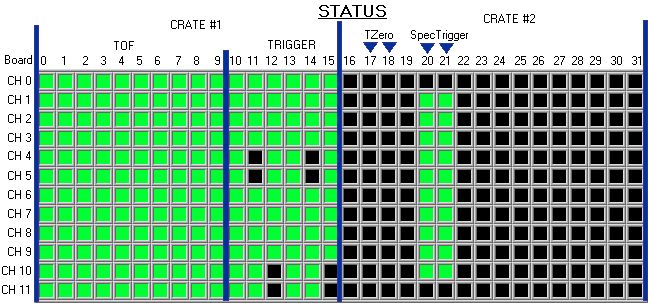
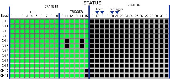
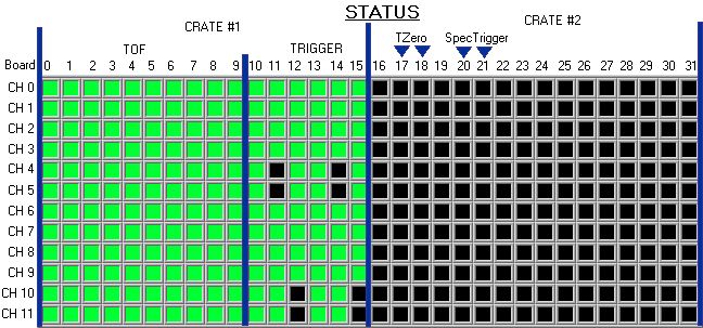
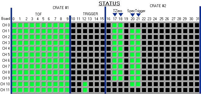
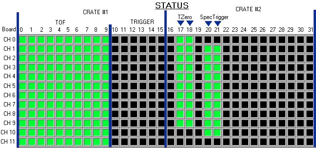
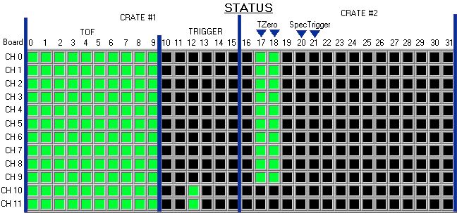
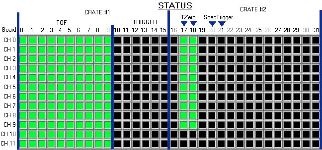
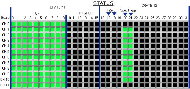
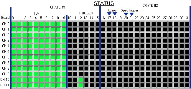
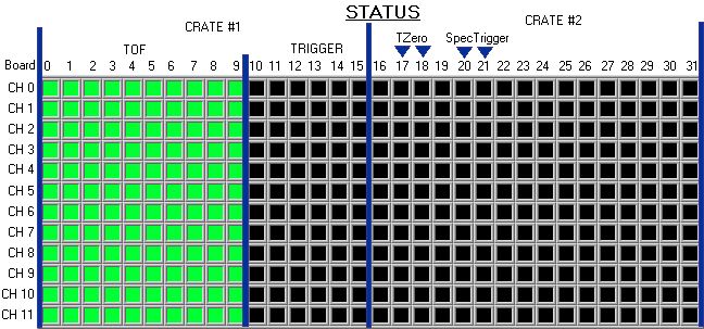
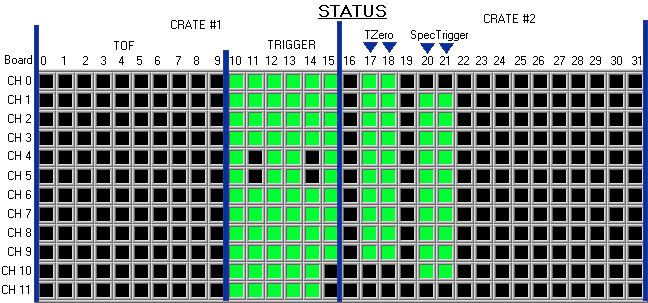
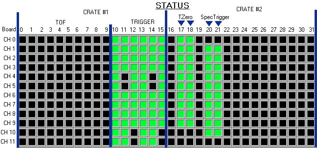
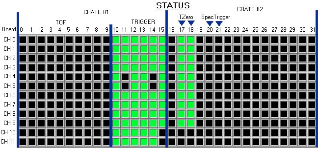
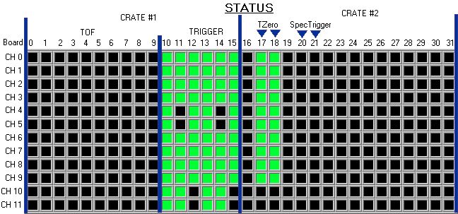
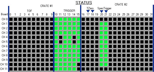
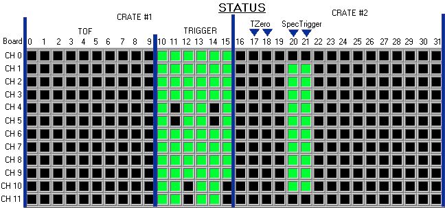
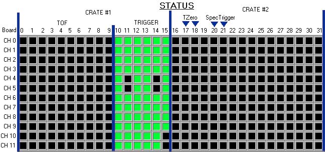
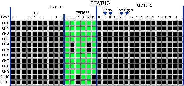
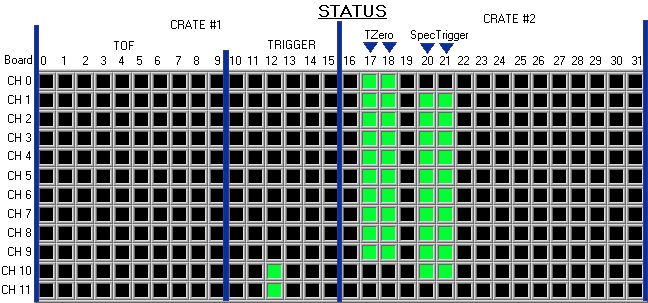
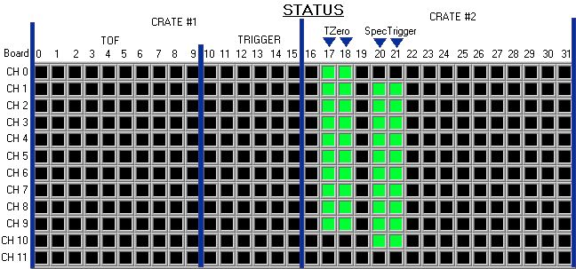
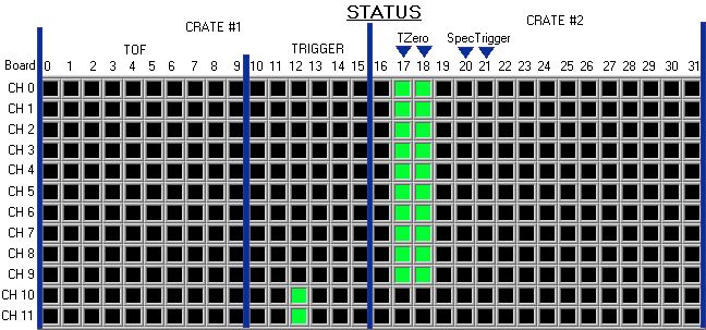
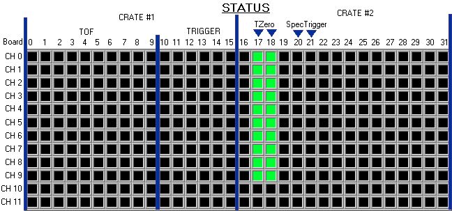
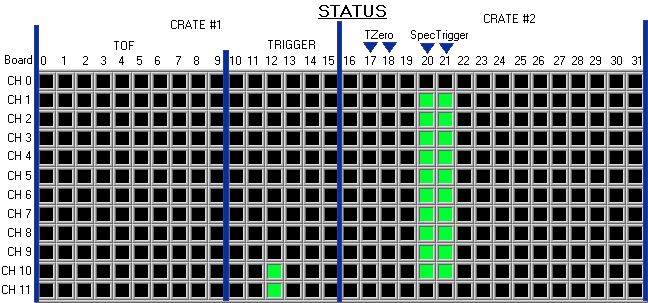
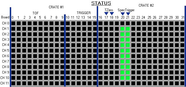
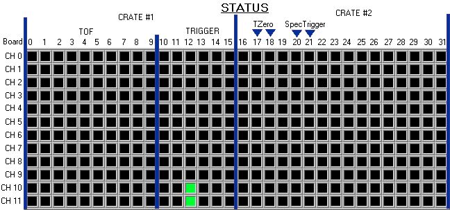
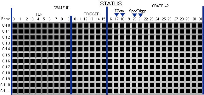
- Checking
the Status for Each Channel
1. The status for each channel is located in a grid in the lower right hand corner of the VI front panel.
2. The color legend is located below the grid.
3.
If the channel is disabled and not black then the channel has tripped. An alarm will sound with a new window. Click the button in the window and call and
expert.
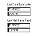
- Checking
the last time the mainframe was read out and data was written to the
database.
1. Locate the fields shown below in the middle of the VI. They report the last time the mainframes were read out and the last time the high voltage was written to the database.
Section
III: Controls
A.
Changing the Setting for a Channel
1. Locate the Controls Frame in the upper right hand corner of the VI front panel
2. Type in the board number of the channel whose settings you wish to change in the field labeled board.
3. Change the channel settings by entering in the requested voltage and/or clicking on the enable button to enable or disable the channel.
4. Click the Send to Mainframe button.
5. The Send to Mainframe button will report “Sending”. When this button returns to its original state, showing “Send to Mainframe”, the data was sent and that board was read out up dating all the monitoring indicators.
6. The vi will lockout the controls until the entire process is complete.
B.
Turning the HV On or Off
1. Locate the HV On and HV Off Buttons in the Controls frame.
2. To turn the HV on, click the HV on button.
3. To turn the HV off, click the HV off button.
4. The vi will lockout the controls until the entire process is complete.
C.
Reading in a template and writing it to the Mainframe
1. Locate the Read Template button in the controls frame.
2. Click the button.
3. The templates should be stored in
E:\Slow Controls\templates\High Voltage
4. Select the desired template.
5. Wait ~10minutes for the settings to be written to the mainframes and read back.
6. The vi will lockout the controls until the entire process is complete.
D. Write the Settings in the Mainframe to a template
1. Locate the Write Template button in the controls frame.
2. Click the button.
3. A window should pop up requesting a filename and location to store the template.
4. The file should be stored in E:\Slow Controls\templates\High Voltage
5. Give a name to the file with the extension .txt
6. Most files are named as the dated they were saved, but this is not necessary.
7. The vi will lockout the controls until the entire process is complete.
E. Read All Data from Mainframe.
1. Locate the Read Mainframe button in the controls frame.
2. Click the button
3. Wait ~10 minutes for the information to be read form the mainframe.
4. The vi will lockout the controls until the entire process is complete.
F. Resetting Current Trips
1. Locate the Reset Current Trips button in the controls frame.
2. Click the button.
3. The vi will lockout the controls until the entire process is complete.
|
Nominal
HV Status TABLE ( X = Detector is
ON) |
|||||
|
Click
to View Status |
TOF |
TRIG |
T0 |
SPECTRIG |
COSMIC |
|
X |
X |
X |
X |
X |
|
|
X |
X |
X |
X |
|
|
|
X |
X |
X |
|
X |
|
|
X |
X |
X |
|
|
|
|
X |
X |
|
X |
X |
|
|
X |
X |
|
X |
|
|
|
X |
X |
|
|
X |
|
|
X |
X |
|
|
|
|
|
X |
|
X |
X |
X |
|
|
X |
|
X |
X |
|
|
|
X |
|
X |
|
X |
|
|
X |
|
X |
|
|
|
|
X |
|
|
X |
X |
|
|
X |
|
|
X |
|
|
|
X |
|
|
|
X |
|
|
X |
|
|
|
|
|
|
|
X |
X |
X |
X |
|
|
|
X |
X |
X |
|
|
|
|
X |
X |
|
X |
|
|
|
X |
X |
|
|
|
|
|
X |
|
X |
X |
|
|
|
X |
|
X |
|
|
|
|
X |
|
|
X |
|
|
|
X |
|
|
|
|
|
|
|
X |
X |
X |
|
|
|
|
X |
X |
|
|
|
|
|
X |
|
X |
|
|
|
|
X |
|
|
|
|
|
|
|
X |
X |
|
|
|
|
|
X |
|
|
|
|
|
|
|
X |
|
|
|
|
|
|
|
|