Last Updated on Friday, July 20, 2001 at 18:23:55. by Author: Edmundo
(General)
-The high voltage is controlled using the high voltage control VI on
the Plastic HV & Camac Controls computer. (The operator's manual is on
the desktop with a help button on the VI front
panel.)
- High voltage to the mainframe should always be on.
- All active Trigger channels need to be enabled, showing green in the
status field.
- If any channels are disabled, determine why by looking at the status
field and make a note in the logbook.
- If an alarm occurs, call Erik at 1036 or at beeper number 7604. Also,
inform Edmundo, and note the alarm in the logbook.
-Turn off the alarm by clicking the alarm button.
-Ensure "zcal" and "HV" (zcalHV) are both open (click
on right mouse button to get pull down menu)
-In zcal window, click on PHOBOS menu and select "open window"
(only option)
-In new "PHOBOS" window, click on HV menu and select
"voltages" (only option)
-In new "zcal HV little popup" click on "load file"
button, select one of the files (call expert):
biraHvps.default.jun99.calXXX
where XXX is a calibration number , then click ok. After few
moments check original HV window, if ok close new windows.Write in logbook
this proceedure.
This shows the scalar information we are currently sending RHIC as a function of time. The legend describes each line.
This RHIC interface is a diagnostic tool for the ZDC. When this window is openedm
This window provides information on the HV state of the tubes for the ZDC. to open this window:
Setting and Checking the Crossing clock time
Whenever the beam changes energy, the crossing clock needs to be changed correspondingly. If it is not changed, then the triggers involving the crossing clock will not work! If the beam is stable (i.e. for > 15 minutes) at one of the energies below, then the following procedures should be used to check that the crossing clock is correct and change it if necessary. Before changing, stop the current run, start another run, do the change during this run, and when the change is done wait a couple of minutes, stop the run and start a new one. Note in the runlog of the transition run what was done. Also, note in the general notebook the changes.
There are three different settings for the crossing clock, depending on the energy of the beam.
The settings of the cc (crossing clock) should be changed only when there is a beam is stable (5 minutes) at one of the above gamma. The gamma of the beam is displayed in the RHIC commissioning monitor (forth row blue and yellow respectively).
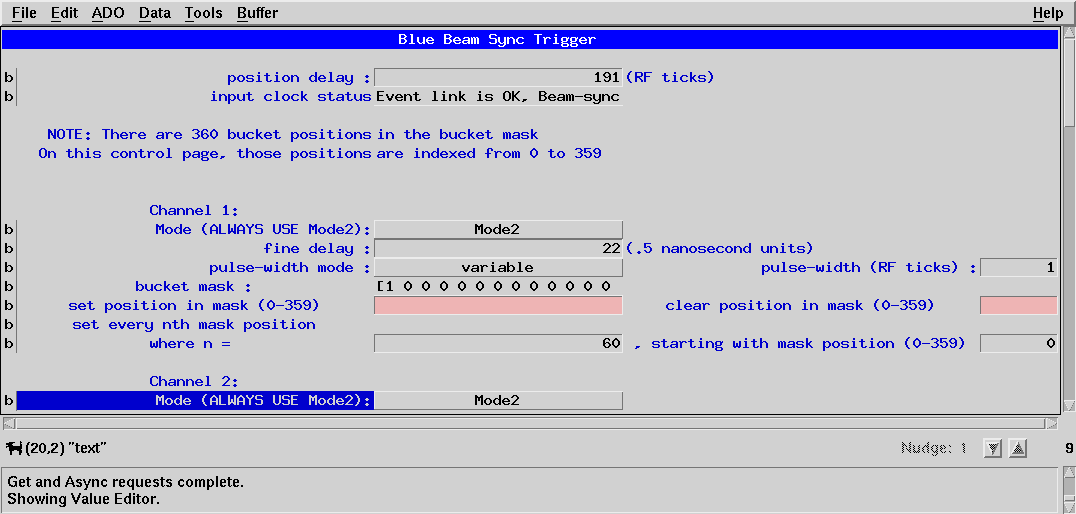
To change the settings of the crossing clock go to the RHIC interface Xterm. Open the window Beam Sync Blue (pet) and the yellow Beam Sync Blue (pet). They window looks like this (yellow with yellow line):
To change the settings click in the corresponding box write the number and hit return;
The settings for gamma at injection (10.25) are for the:
The settings for gamma 30:
The settings for gamma 70:
The rest of the numbers should remain the same.
To check this time, look at the oscilloscope between the silicon and on line monitors. The upper signal is the PP. The lower signal is the crossing clock. The crossing clock should lay approximately around either of the vertical lines.
Please send all comments and suggestions regarding this page to Edmundo. |