
Expert’s Guide to the Time Zero.
V. Installing/ Removing Time Zero Counters
A. for PR01
The counters can be installed and removed with ease but great care needs to be taken due to the close proximity of the beam pipe and other detectors. The cables for the counters are routed through the center of the cerenkov detector stand. There is a foam barrier between the cables and the beam pipe. The counters are mounted in a ultem frame. Set screws keep the counters from sliding horizontally in the apparatus.
Installation and removal requires two people. One person is required to hold the counter while the other person has to unscrew the outer clamps. The cables should be unplugged prior to removing the side clamps. The clamps are removed by unscrewing the white screws, as seen in picture, on the top (bottom) and side of the front and back of the mount. The counter can be put into place or removed at this point. Then the clamps should be put back in place, and if the counters are being installed, the set screws should be tightened.
B. For PR03 (and beyond)
The procedure is basically the same as it was for PR01, except that there are more counters.
VI. Moving T0s to a New Position
There are 3 arrangements for the T0 counters as shown below.
For Au-Au: we have the arrays set up behind ring 3 on both the positive and negative sides
For d-Au: we have the Positive array behind ring 2 (on the positive side) and the negative array behind ring 3( on the negative side).
For p-p: we have the Positive array behind ring 2 (on the positive side) and the negative array behind ring 1 (on the negative side)
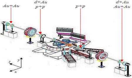
Picture of PHOBOS with each T0 configuration
When moving the counters the HV cables and signal cables from the patch panel must be rerouted.
The HV cables are secured on top of the plastic cover over the beam pipe. The signal cables are routed through the silicon plastic tray from the patch panel on the trigger rack to the tubes.
P-Side: The excess on the P-side is located on the overhead tray running from the central cable tray to the side of the tunnel wall (See picture below). Reroute as much cable as needed to go from current position to behind ring 3 and use the holes drilled in the plastic cover to secure the cables. The signal cables need to be rerouted in the silicon plastic cable tray (with Rachid or Gerrit's help) to the new position(s).
N-Side: The HV cable excess is secured on top of the plastic cover over the beam pipe. Reroute the cable to the position behind ring 1 securing it along the plastic cover and plastic tray as the cable is draped over the side. The signal cables need to be rerouted in the silicon plastic cable tray (with Rachid or Gerrit's help) to the new position(s).
STEP BY STEP DETAILS TO MOVE T0S