PROCEDURE FOR MOVING THE T0s
Preparation
for relocating T0s:
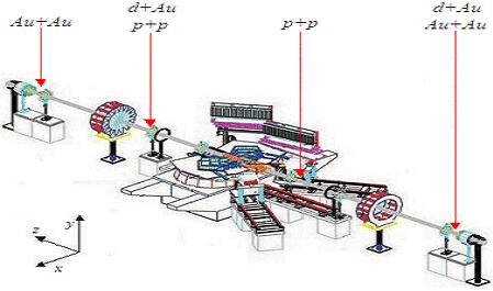
1) Locate new T0 position for the run:
e.g. For pp -: P Side - directly
behind the 2nd set of ring counters; N Side – behind the 1st
set of ring counters. See figure.
2) Take a look on top of the cable trays, which house the T0 cables and locate the T0 cables on both sides.
3) Determine the best way to reroute the
cables to the new position. There will be more than sufficient
slack to move the T0s to the pp positions.
4) Determine how best to secure the
cables when the T0s are later put in place. Note that you will need to follow a similar approach to how they currently secured.
5) T0 Storage Box located in Trailer
outside Building 1010. One large box contains many (20) small individual T0 boxes.
6) Go through the steps outlined below in mock fashion so that you know where and what the various parts of the T0 stands are.
7)
Make sure Rachid/Gerrit will be available during the time of rerouting the
cables so that they can assist in rerouting the cables in the plastic trays.
Procedure for removing the T0s from
the array
# of
People needed : 2
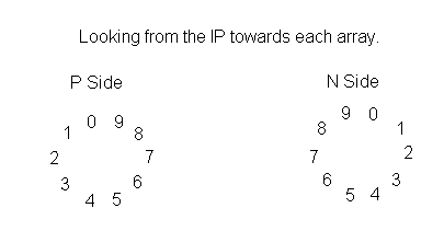
0) Person 1 will record/verify positions of tubes in the array so reassembly will result in the T0s being replaced in the same positions as during d-Au. Specify convention e.g. “looking at the T0 Pside array from the IP : this is the arrangement”. See example below.
e.g. of Position of T0s in array
when looking from the IP
9 0 8 1 7 2 6 3 5 4For the current (04/06/2004 and all of PR04) orientation see here.
1)
Person 1 & Person 2 will be positioned on either side of the beam pipe.
2)
Person 1 & Person 2 carefully disconnect cables from T0s and secure them
away from the Beampipe, 1 at a time, each removing 1 set of T0 cables at a
time on each side of beam pipe to maintain balance. Be very careful not to let
the cables bang the beam pipe.
3) Person 2 loosens/removes
tube holder clamps and set screws from the bottom T0 (T0position#5)
while Person 1 holds tube in place.
4)
Person 2 removes the tube moving radially away from the beam pipe
5)
Person 2 places tube in box
6)
Replace tube holder clamp and re-secure with appropriate screws.
7)
Person 1 loosens/removes tube holder clamps and set screws from the bottom T0
(T0position#4) while Person 2 holds tube in place.
8)
Person 1 removes the tube moving radially away from the beam pipe
9)
Person 1 places tube in box
10)
Replace tube holder clamp and re-secure with appropriate screws.
11)
Repeat 3-10 four times such that one tube is removed on either side of the
beampipe each time to maintain balance.
e.g. 4 then 5, 3 then 6, 2 then 7 etc.
This procedure is for moving
the T0 array with the T0 tubes already removed and the aluminium stand already
in the new position behind ring 1 on the N side or behind ring 2 on the Pside.
Disassembly of array at current
position on the N side behind ring 3.
People
involved : Person 1, Person 2
1) Person 1 and Person 2 will be positioned on either side of the beam pipe.
2) Person 1
& Person 2 carefully loosen the Inner screws for the top half of the
array.
3) Person 1
& Person 2 carefully remove the outer screws coupling the two array halves
together, 1 screw at a time for the top half of the array.
4) Person 1 & Person 2 carefully
remove the top half of the array.
5) Person 1 will lower support base
to lowest point by turning the adjustment screw; the furthest distance should
be about 12"
6) Person 2 will unattach the bottom
half circular array from the base unit holder with the 1024 .75" screws
while Person 1 holds it together.
7) Person 1 will slide the (half)
circular array base from the RHS/LHS from up to down to remove the bottom half
of the array. (RHS/LHS
8) Person 1
will put Circular base in a temporary safe place.
9) Person 2 will uninstall the base
unit (Ultem plastic) to the Aluminium frame using the 1024 1" plastic
screws, ONLY if the new position does not already have one installed.
End of Array Uninstallation
Assembly of array at new position on
the N side behind ring 1 or P side behind ring 2
Installing Array on New Aluminium
stands
0) Prepare the bottom half of the
array e.g. Attach the paper cut out guide
to the bottom half of the array. (Paper cut outs available in the TOF cubicle
in Chemistry)
1) Person 1
and Person 2 will be positioned on either side of the beam pipe.
2) Lower support base to lowest point
by turning the adjustment screw; the furthest distance should be about
12" - Person 1
3) Install the base unit (Ultem) to
the Aluminium frame using the 1024 1" plastic screws - Person 2
4) Retrieve base of Circular holder
from temporary safe place - Person 1
5) Person 1 will slide the (half)
circular array base from the RHS/LHS from down to up into the required
position and hold it there. (RHS/LHS depending on which side has more room)
6) Person 2
attaches the bottom half circular array to the base unit holder with the 1024
.75" screws while Person 1 holds it together.
7) Person 1 raises and adjusts base
unit to line up array properly under the beampipe with the turn screws using
the paper cut outs as guides.
8) Get top half of array - Person
1/Person 2
9) Person 1 & Person 2 carefully
place the top half of the array on top of the bottom half and make sure the
grooves match up perfectly
10)Person 1 & Person 2 tighten
Outer screws coupling the two array halves together, one screw at a time [832,
0.5"]
11)Person 1 & Person 2 tighten
Inner screws [832, 1"]
12)Person 2 removes Cut out guide
End of Array Installation
Begin T0 insertion
13) Loosen
Bottom 2 tube holder clamps so that T0 can slide in from the direction
with most room (LHS/RHS) - Person
1 & Person 2
14) Get 1
tube - Person 1
15) Person 1 retightens tube holder
clamp and set screw
16) Verify that about 1.5" of
tube is on either side of the array holder
17) Get 1 tube - Person 2
18) Person
2 retightens tube holder clamp and set screw
19) Do #16
20) Repeat steps 13-19 four more
times, inserting tubes at the bottom of the array then inserting each time one
closer to the top.
Once T0s are installed
1) Make sure all T0s in each array are
lined up (to your eyes approximation). Try to align them about 0.5” (finger
space) away
from the ring enclosure.
2) Measure the distance of the front of the radiators to the ring enclosure.
3) Verify that the ring enclosure width
is ~5.5”.
4) Measure the distance of the front of the Ultem array to the front surface of Radiator.
5) Measure the distance of the Back of the Ultem array to the back of the PMT (magnetice shield case).
6)