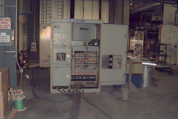
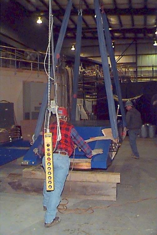
Assembly of the magnet at the AGS (near the EVA experiment) November/December 1998
|
|
|
|
|
|
|
|
|
 |
 |
 |
 |
 |
 |
 |
 |
 |
 |
 |
 |
![]() Picture of the Phobos
Magnet Stand at BNL on November 4, 1998
Picture of the Phobos
Magnet Stand at BNL on November 4, 1998
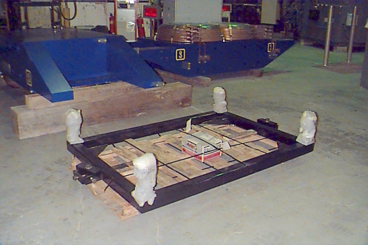 |
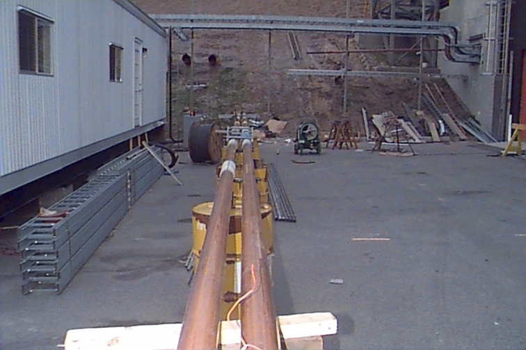
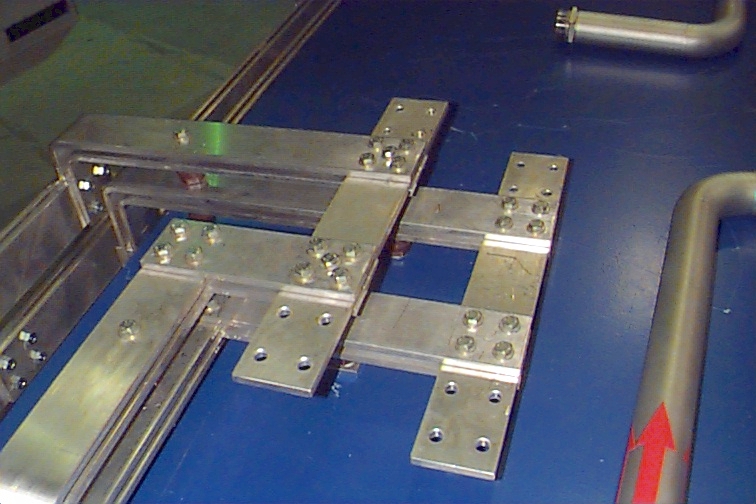
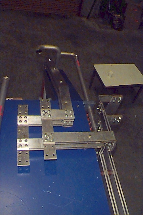
Phobos Magnet Stand at BNL. The four columns bolt into the lower yoke and give vertical adjustment. The two frames on the sides tie the frame down to the tunnel floor and provide for horizontal adjustment. |
 Pictures of the
Phobos Magnet arriving at BNL on November 3,
1998
Pictures of the
Phobos Magnet arriving at BNL on November 3,
1998
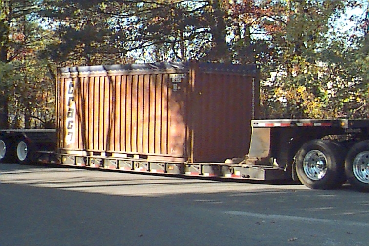 |
The Phobos Magnet making its entry into BNL! |
 |
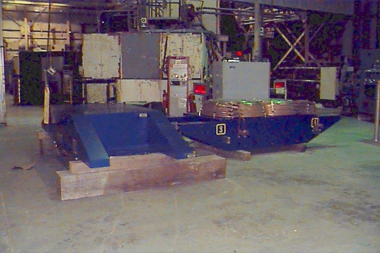
The upper and lower yoke of the Phobos Magnet were transported in two different containers. Shifting of the yokes inside the container was prevented by a wooden structure. |
 |
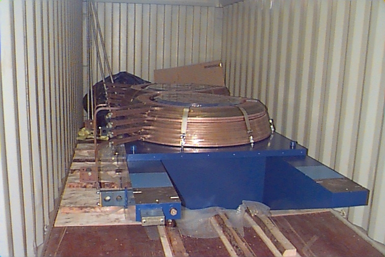
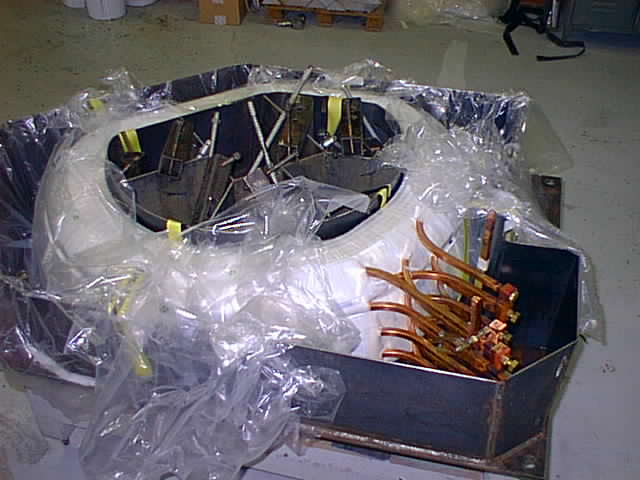
A closer look at the top of the lower yoke piece. The (unpainted) pole surface is protected by a plastic sheet. |
 |
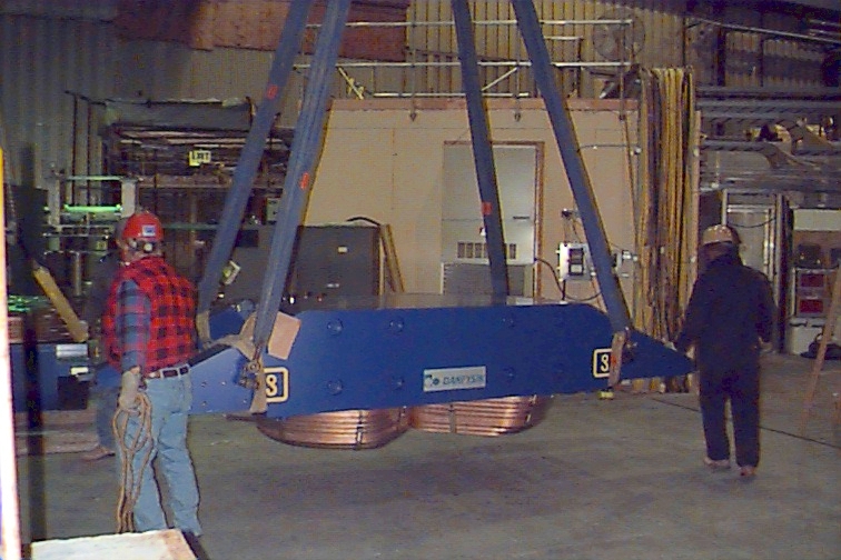
The lower yoke is unloaded from the container onto the AGS floor. |
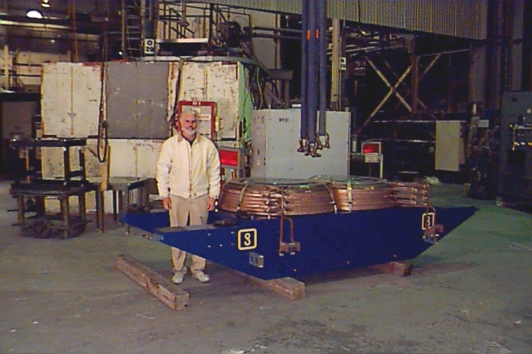 |
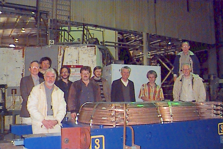
Phobos Collaborator and photographer Steve Gushue posing with the magnet! |
 |
|
 |
|
 |
|
 |
![]()
 Pictures of the
Phobos Magnet Yoke pieces taken on October 4,
1998
Pictures of the
Phobos Magnet Yoke pieces taken on October 4,
1998
 |
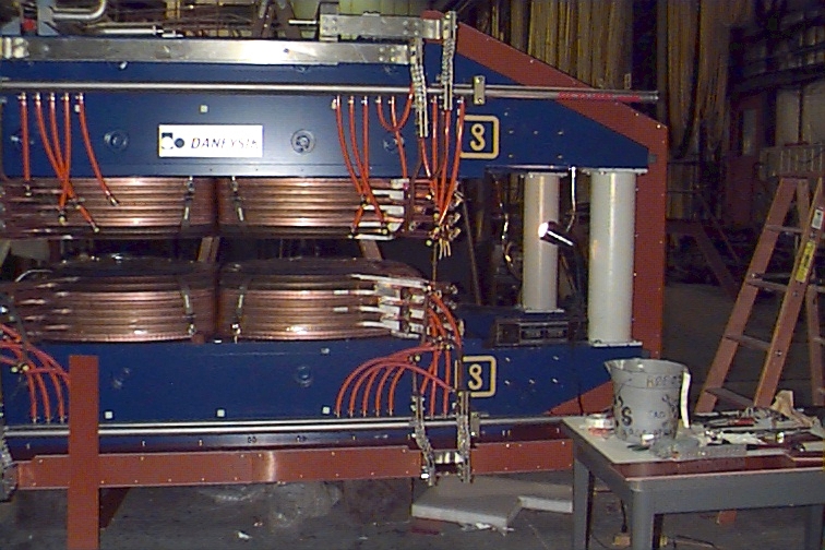
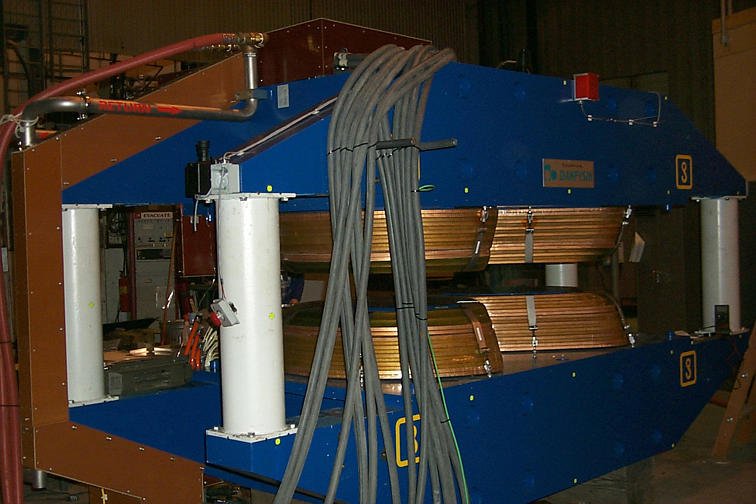
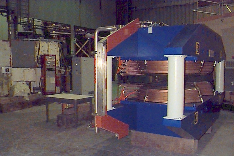
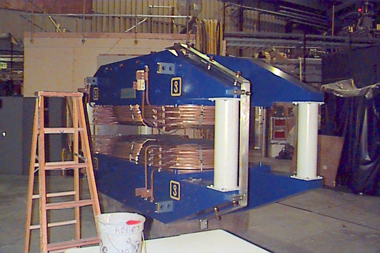
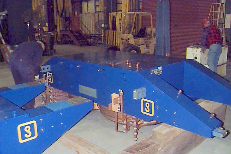
The fully assembled Phobos Magnet |
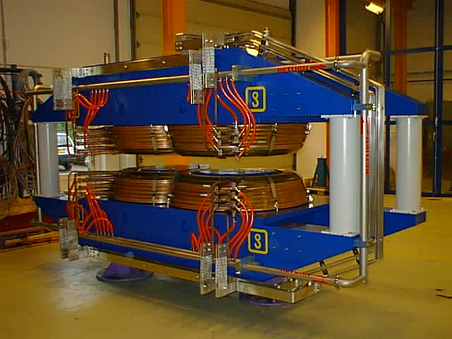 |
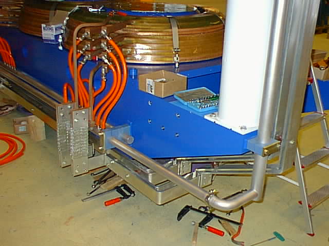
This picture shows how the fully assembled manifolding and buss-bars look like. |
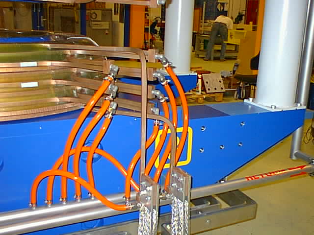 |
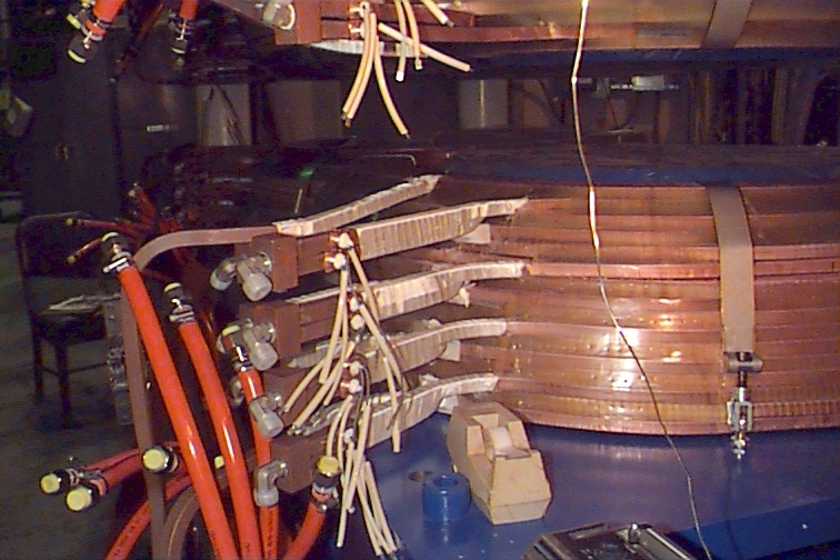
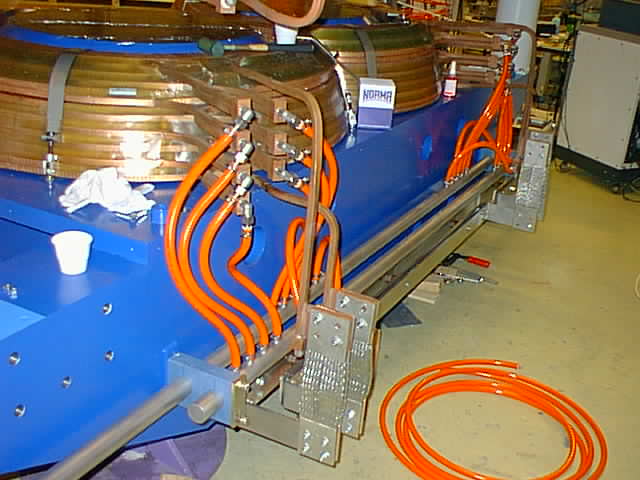
Detailed close-up of the manifolding for one of the poles. Note that the copper conductor of the suppy/return power is also water cooled all the way from the buss-bar connection. The hoses are of different lengths. They should be fitted appropriately. |
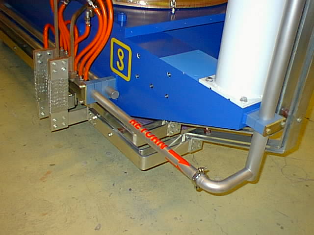 |
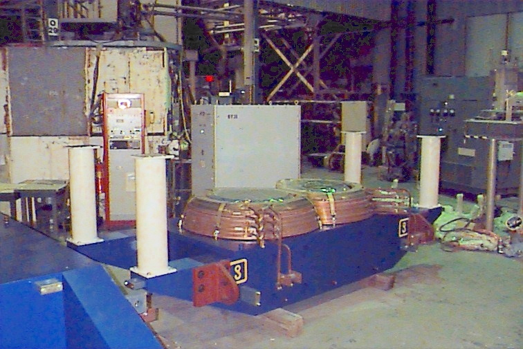
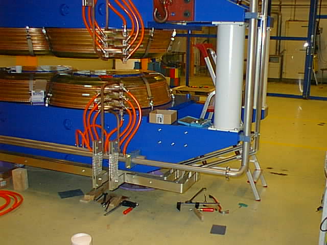
Detail of the manifolding and buss-bars in the corner. |
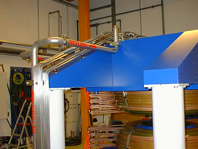 |
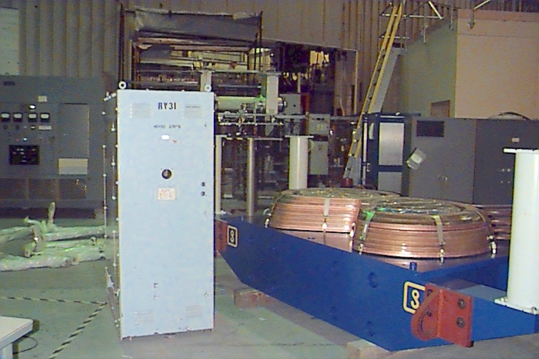
A picture of the return manifold and of the electrical connections. Note that the electrical connection is at two different levels. |
![]() Pictures of the
Phobos Magnet Yoke pieces taken on September 28,
1998
Pictures of the
Phobos Magnet Yoke pieces taken on September 28,
1998
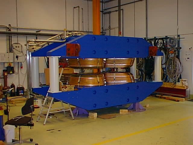 |
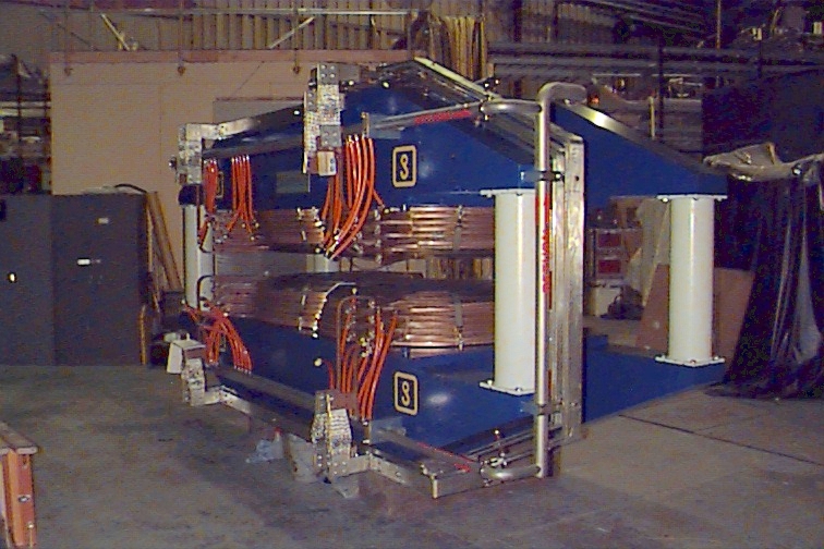
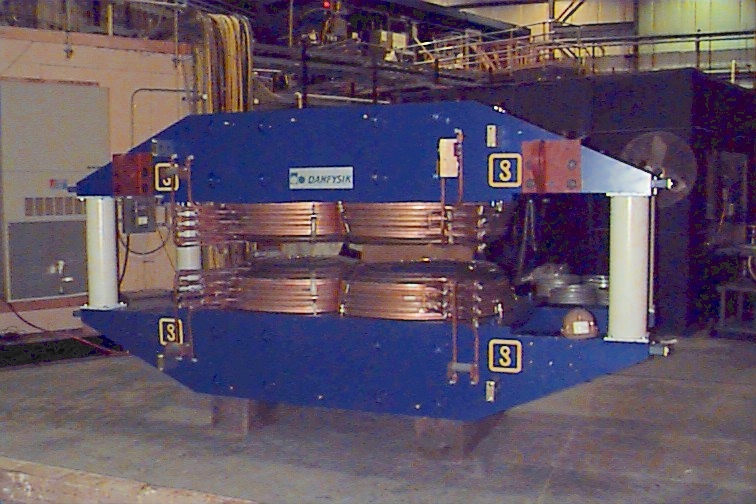
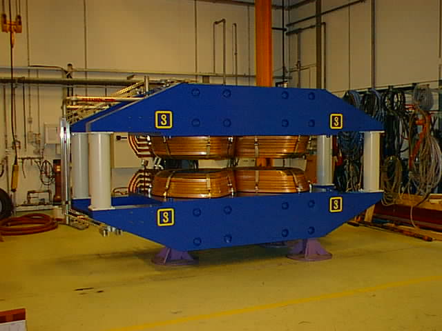
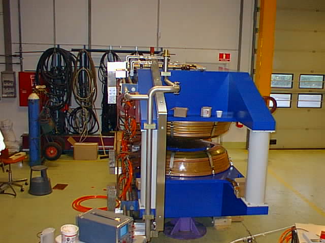
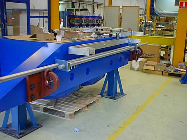
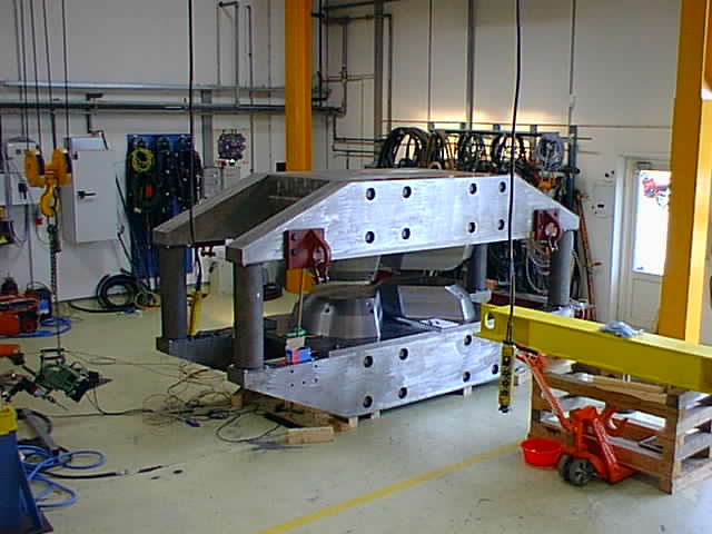
The Phobos Magnet! |
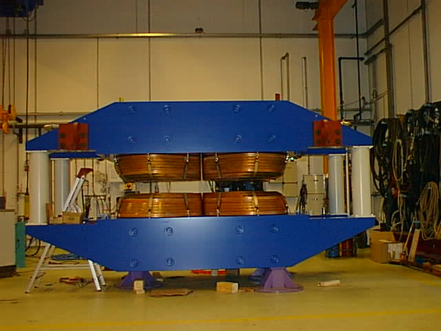 |
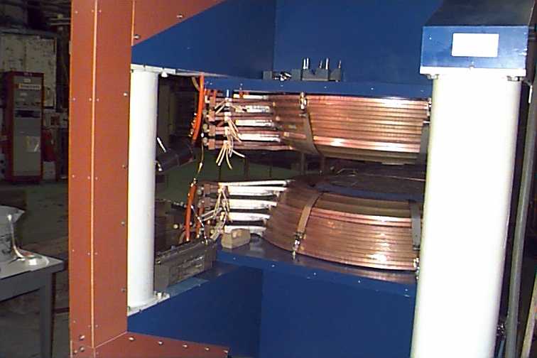
The Phobos Magnet from the side of the interaction region. |
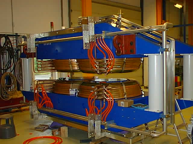 |
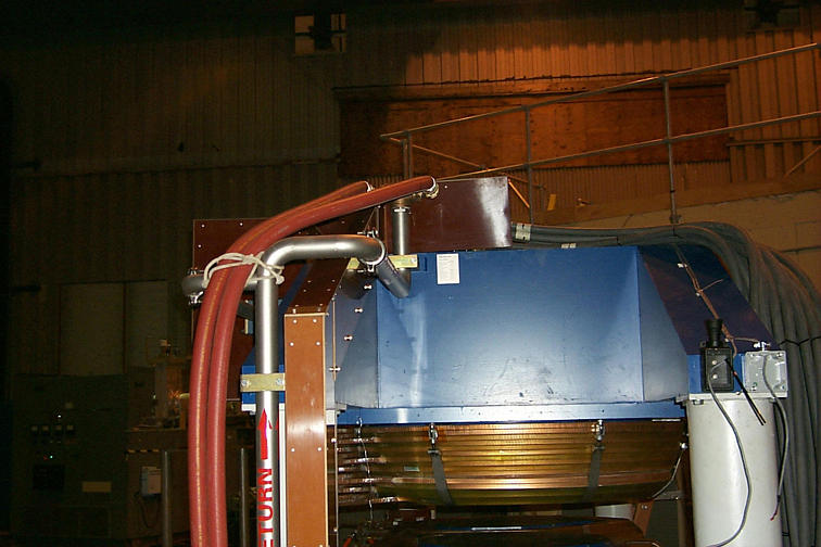
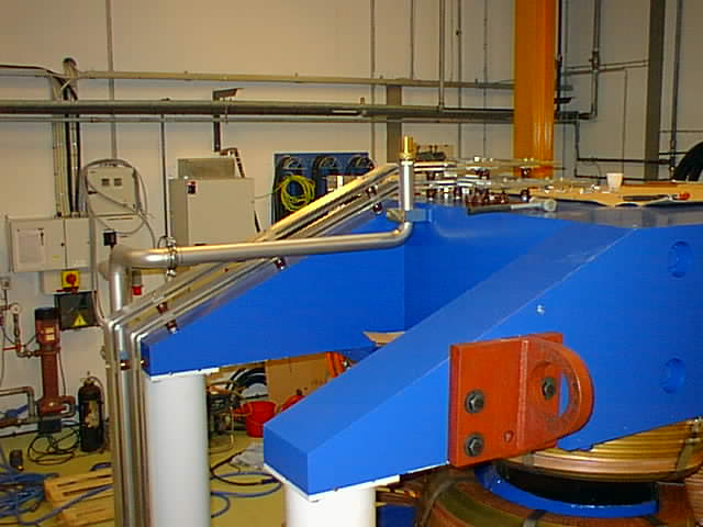
The orange tubes feed the cooling water to the four coils. Note how the manifolding goes along one of the columns, so as not to shadow any TOF elements. |
 |
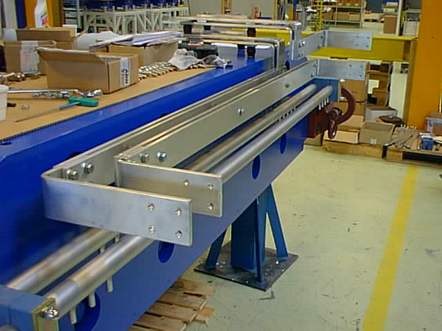
A more detailed look at the coil connections. |
 |
A detailed look at the other coil and also showing how the manifolding and bussbar is tucked underneath the magnet. |
 |
|
 |
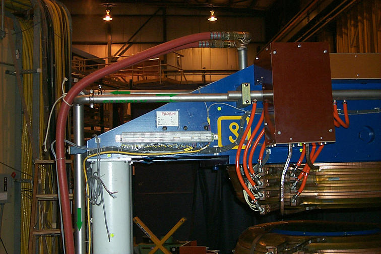
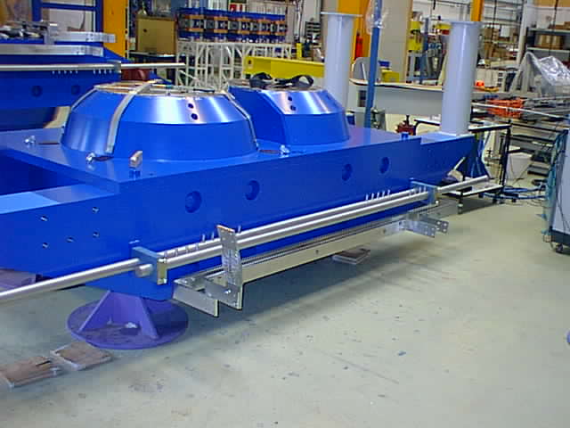
A look at one of the cooling water feeds and the electrical connections. The water feeds are on both sides of the magnet, the electrical connection is on the outer wall side of the tunnel. |
 |
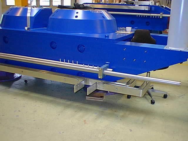
Another look at the manifolding, from the outer wall side. |
Pictures of the
Phobos Magnet Yoke pieces taken on September 21,
1998
 |
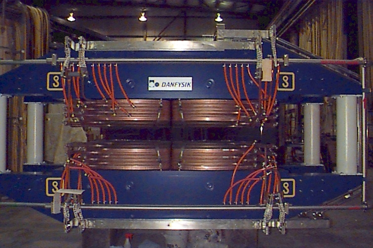
The upper yoke of the Phobos magnet. The bussbar and manifolding are clearly visible. |
 |
Closer look at the bussbars. The bussbars consist of two tinned copper conductors. Note the electrical connections that will be made on top of the yoke. |
 |
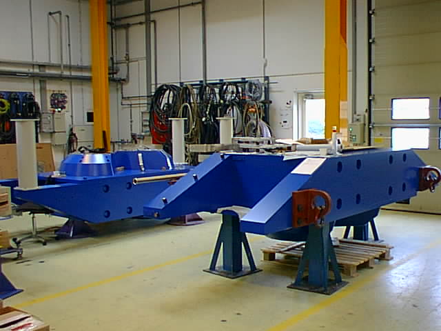
The painted lower magnet yoke. |
 |
The lower magnet yoke. The nipples on the manifolding will connect the cooling tubes to the coils (the coils are not installed on this picture). There are five in and outlet connections per coil. |
 |
Note the way the bussbar goes around the corner. Both the positive and negative terminal of the electrical connections have to follow the same path to cancel any additional magnetic field coming from the bussbar as much as possible. |
 |
One more look at the upper yoke. |
 |
![]() Pictures
of the Phobos Magnet Coils taken on September 3,
1998
Pictures
of the Phobos Magnet Coils taken on September 3,
1998
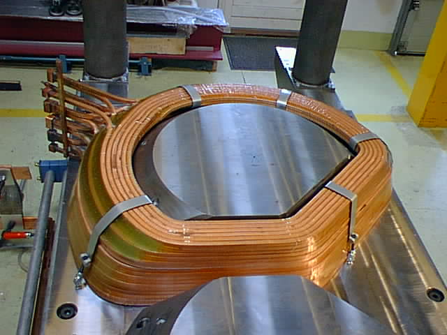 |
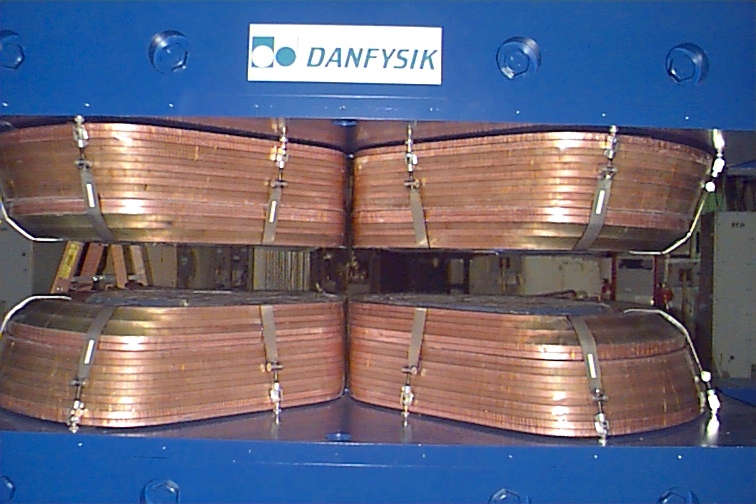
Impregnated coil mounted on one of the pole tips. Straps hold the coil down and you can see the coil connections on the left. The water connections will have a 45deg elbow, bending the waterflow down towards the manifolding which runs horizontally (on the left in the picture). |
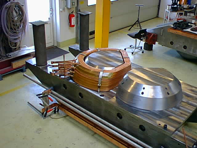 |
More of the coil on the pole tip. You can see the upper yoke sitting on a stand on the right in the picture. |
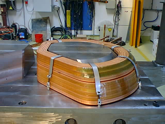 |
A view of the coil from the vertex position. |
![]() Pictures of the
Phobos Magnet at Danfysik taken on August 18,
1998.
Pictures of the
Phobos Magnet at Danfysik taken on August 18,
1998.
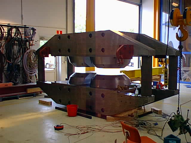 |
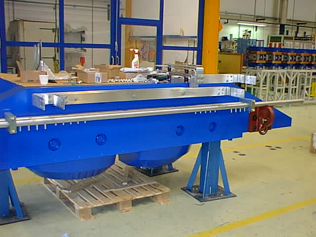
The unfinished yoke. Note the large holes in the yoke that are used to keep the three separate yoke pieces together. |
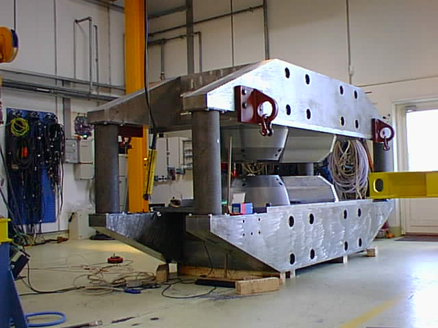 |
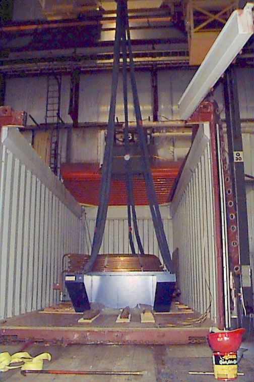
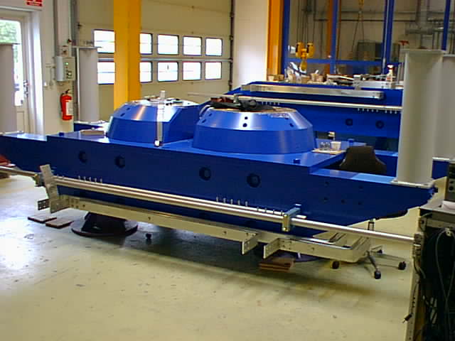
40 tonnes of beauty. |
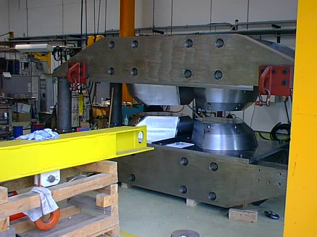 |
Notice the tapers on the pole tips. |
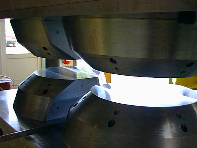 |
The yoke gap. |
 |
The magnet standing in the Danfysik shop. |
 |
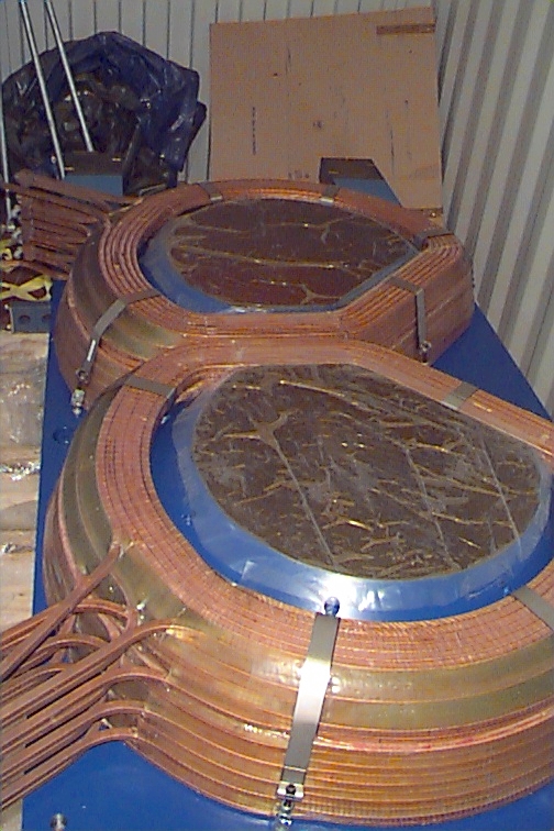
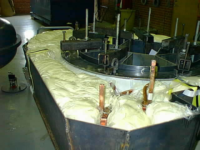
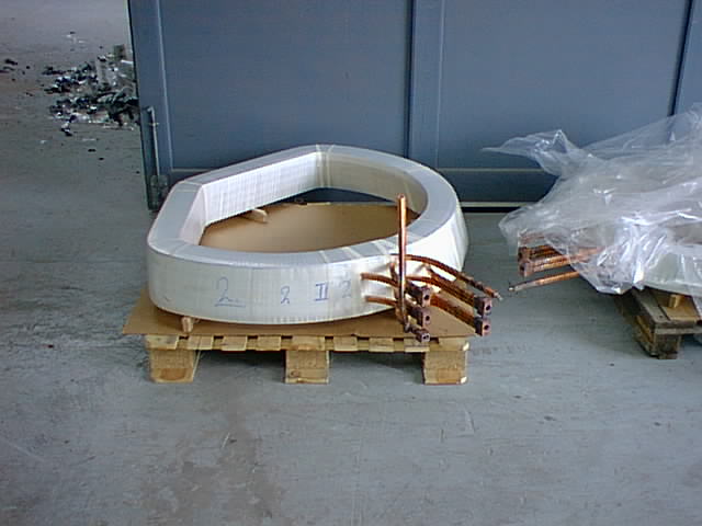
Coil just befor impregnation. |
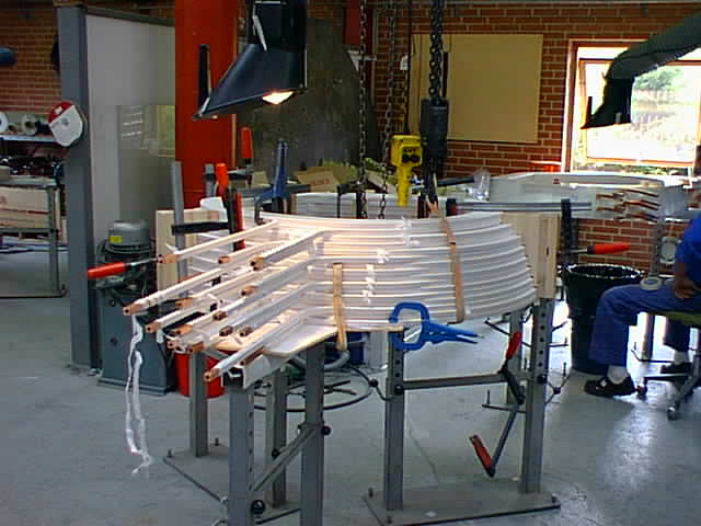 |
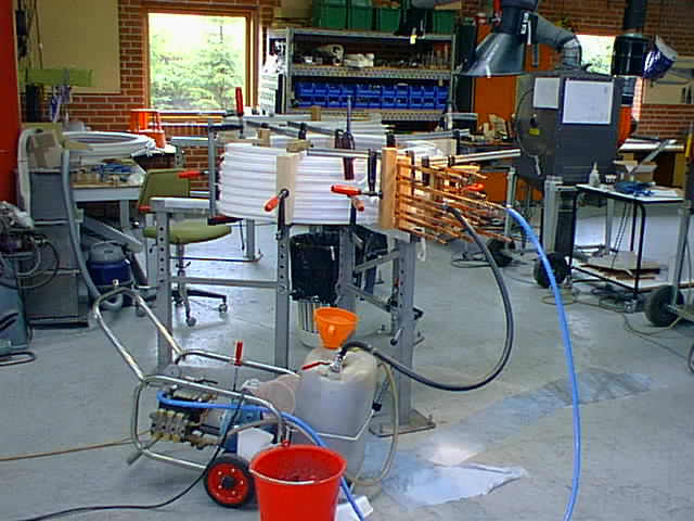
A Coil on the coil winding equipment. There was some concern that the coils would turn out to be higher due to 'keystoning' problems. This turned out to be a minor effect, the coils are only 3mm higher than originally designed. |
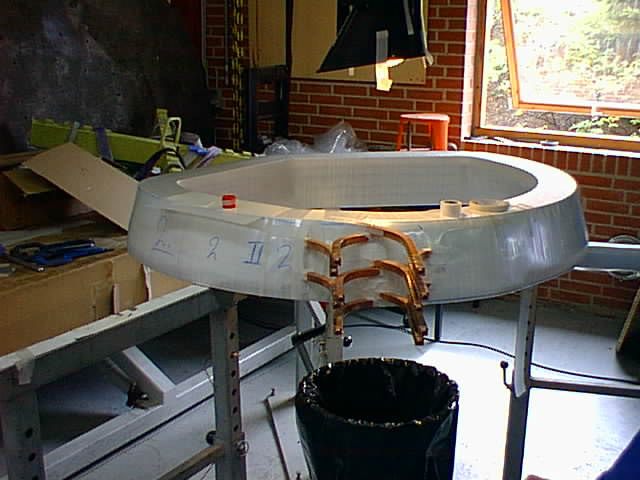 |
A Coil is being insulated just before the impregnation. |
 |
|
 |
|
 |
|
 |
|
 |
Last edited: Friday, February 04, 2000 by Patrick Decowski.