No crosstalk between Twinax cables
Run 12523. Only one T0P0 versus only one T0N5.
(06/02 14:33, A. Sukhanov) All TC signals disabled by
pulling out cables from F11. The Time Calibrator (TC) is connected to only one
channel on negative T0 (T0N5). The free running generator 1 MHz is connected to
one channel of positive T0 (T0P0). TC is set to 80/40 to have less pulses
outside of TDC range, with this setting there are only 2 pulses in its high
resolution range.
Signals:
T0P0 is connected to FB TDC17[0]. Free running generator 1MHz.
T0N is connected to FB
TDC17[1] and VME VTDC0[1].
T0P is connected to FB
TDC17[2] and VME VTDC0[0].
T0N5 is connected to FB TDC17[3]. Time Calibrator.
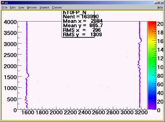
T0P0 vs T0N5 using FASTBUS TDC. Two calibrator pulses
Draw("TDC17[2]:TDC17[1]>>hT0FP_N","","colz")
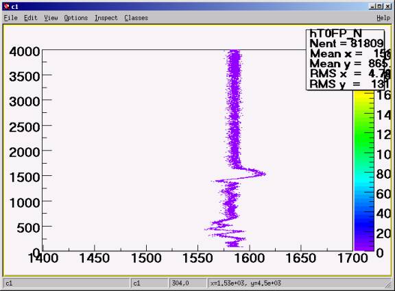
Zoom of the first line of the previous fig.
The zigzag at Y=500: effect of the trailing edge of the generator pulse
The bump at Y=1500: effect of the leading edge of the generator pulse
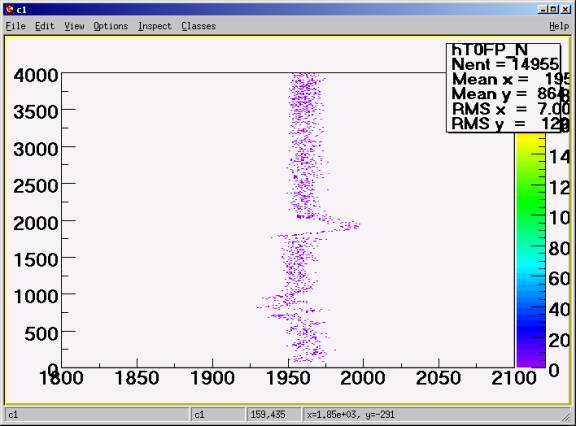
Run 12517. All TC enabled.
Draw("TDC17[2]:TDC17[1]>>hT0FP_N","","colz")
The effect does not depend how many neighbors are fired.
Run 12524,12525,12526. Twinax is directly connected to TDC17
The twinax is connected to TDC17 using 2m of separated twisted pairs.
The shield is not connected.
The generator is 4 MHz.
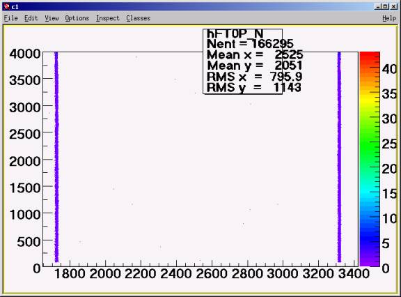
chain.Draw("TDC17[2]:TDC17[1]>>hFT0P_N","","colz")
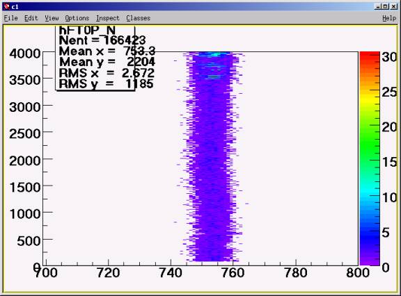
chain.Draw("TDC17[2]:TDC17[1]>>hFT0P_N","","colz")
First TC position.
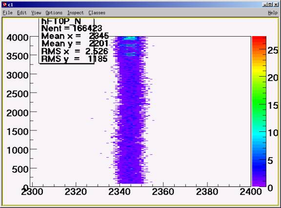
chain.Draw("TDC17[2]:TDC17[1]>>hFT0P_N","","colz")
Second TC Position.
There is no cross talk between pure twinax cables.
Run 12528. Effect of 2m of SpectraStrip
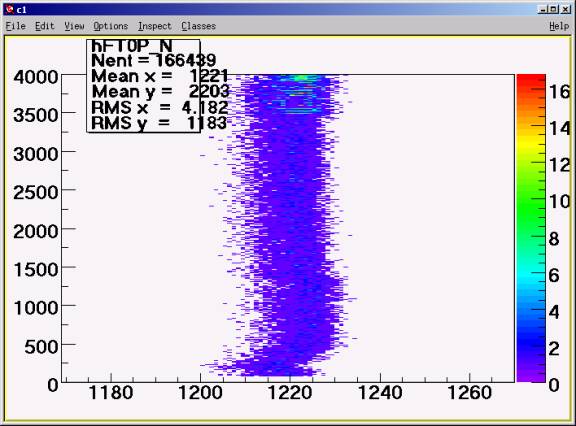
chain.Draw("TDC17[2]:TDC17[1]>>hFT0P_N","","colz")
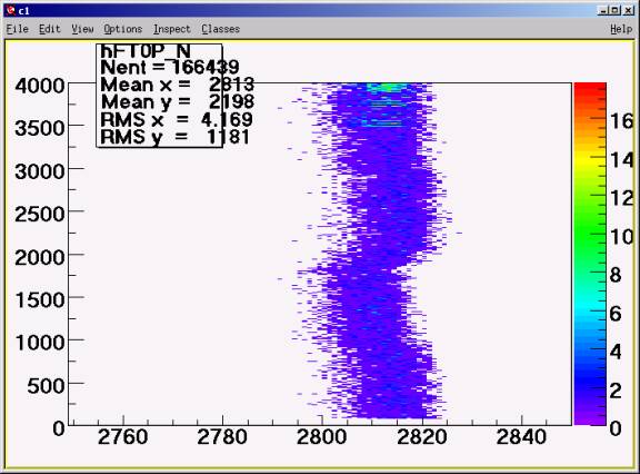
chain.Draw("TDC17[2]:TDC17[1]>>hFT0P_N","","colz")
The crosstalk from the leading edge is a very narrow kink at Y=2800,
The broad hump from Y=1000 to 1700 is due to the trailing edge. We can conclude that trailing edge is long.
Adding 2m of SpectraStip results in shift by 250 ps due to the crosstalk.