Effect of the Interlaced Grounding on a Cross Talk
Last modified June 24, 2003
Run 12549. Victim: pair 4,
aggressor: pair 5. Little crosstalk due to the cable.
Run 12551. Victim: pair 4,
aggressor: pair 3. Little crosstalk due to the cable.
Run 12549. No crosstalk
between channels 14 and 15 of the discriminator 3412.
Run 12552,3. Check if the
cable adds to the crosstalk, as seen in run 12539.
The cable does not add to the
cross talk!
Run 12560. Victim at ch. 0,
aggressor at ch. 4. No crosstalk
Run 12562. Using individual
wires. Discriminators have no crosstalk
Run 12561. Combined crosstalk
in the discriminator and the interlace-grounded cable
Crosstalk is negligible, 25
ps.
Run 12561. Using standard
cable.
Combined crosstalk in the
discriminator with the standard cable is 70 ps.
Testing real cables from
positive Padlles and Cherenkovs
Run 12564. Standard cables.
Crosstalk = 700 ps.
Crosstalk is 700 ps. Such data
are un-analyzable.
Run 12566. Interlace-grounded
cable. Crosstalk = 500 ps.
Run 12569. Grounding on both
ends. No effect.
Setup

The cable. Distribution of the ground between pairs in the twisted pair cable.

Small adapter card combining 2 interlaced cables to one normal socket
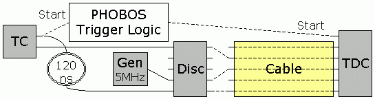
The discriminator 3412 is used as a signal source. The different lines of the cable were connected to the discriminator using short 4 cm twisted pairs.
Run 12549. Victim: pair 4, aggressor: pair 5. Little crosstalk due to the cable.
Disc 3412.
Victim: disc.00 -> cable.05 -> TDC17.20
Aggressor: disk.14 -> -cable.06 -> TDC17.21
Start: disc.15 -> cable.15 -> TDC17.31
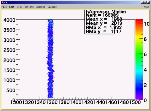
Draw("TDC17[21]:TDC17[20]
Crosstalk = 2 counts.
This setup have been repeated in run 12554 and showed similar picture. The pair TDC17[20] in
Run 12549 had wrong polarity.
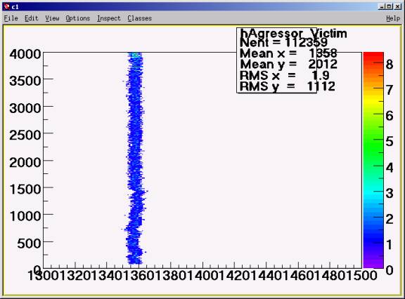
Draw("TDC17[21]:TDC17[20]
Run 15557.
In this run the cable was replaced by individual wires.
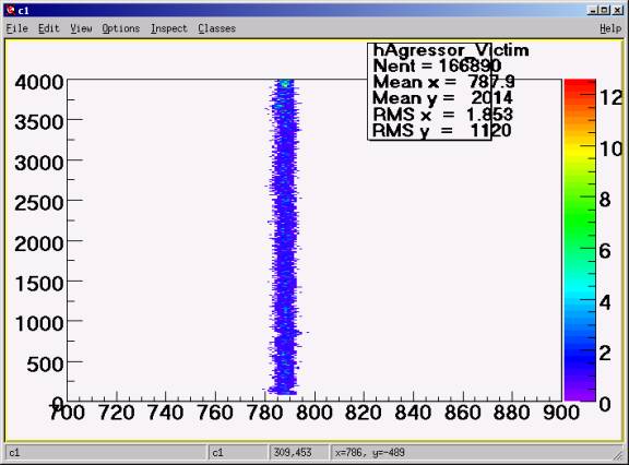
Draw("TDC17[21]:TDC17[20]
The peak is shifted left by 611 counts = 15.3 ns.
(Measured on the scope: 13 ns on even lines and 10 ns on odd lines)
By the way the difference with run 12554 is small.
The peaks are not due to a crosstalk in the cable but in the TDC!
Run 12551. Victim: pair 4, aggressor: pair 3. Little crosstalk due to the cable.
Disc 3412.
Victim: disc.00 -> cable.05 -> TDC17.20
Aggressor: disk.14 -> -cable.06 -> TDC17.19
Start: disc.15 -> cable.15 -> TDC17.31
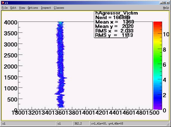
Draw("TDC17[19]:TDC17[20]
Cross talk = 5 counts. Strange. Need to repeat it. Crosstalk in TDC?
This setup have been repeated in run 12555 but using individual pairs instead of the cable:
Run 12555
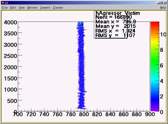
Draw("TDC17[19]:TDC17[20]
The shape is the same (keep in mind that the front/tail is shorter now due to shorter wires) that means this is not a cable effect.
Run 12549. No crosstalk between channels 14 and 15 of the discriminator 3412.
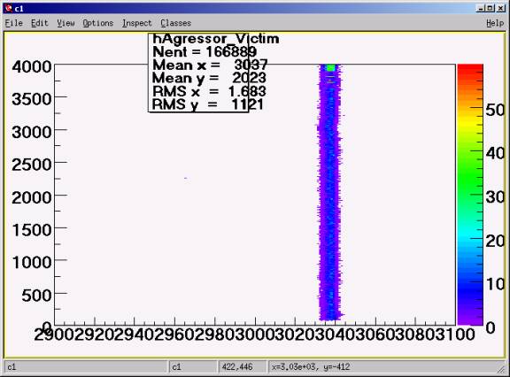
Draw("TDC17[21]:TDC17[31]>>hAgressor_Victim"
This is interesting. The channel disc.30 does not affect the disc.31 at all!
Run 12552,3. Check if the cable adds to the crosstalk, as seen in run 12539.
Victim: disc.0->cable.0->TDC17.16.
Aggressor: disc.1->cable.1->TDC17.17.
Start: disc.15->cable.15->TDC17.31.
As in all previous runs there the cable is connected to the disc. using short wires
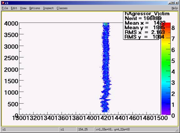
Draw("TDC17[17]:TDC17[16]
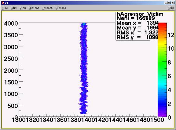
Run 12553.Draw("TDC17[17]:TDC17[16].
The same as before but cable connected to disc. directly to compare with run 12539.
Crosstalk ~ 5
In the run 12539 (individual wires instead of cable) the picture was very similar.
The cable does not add to the cross talk!
Run 12560. Victim at ch. 0, aggressor at ch. 4. No crosstalk
Disc 3412.
Victim: disc.00 -> cable.00 -> TDC17.16
Aggressor: disk.04 -> cable.04 -> TDC17.20
Start: disc.15 -> cable.15 -> TDC17.31
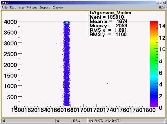
Draw("TDC17[20]:TDC17[16]
Run 12562. Using individual wires. Discriminators have no crosstalk
Victim: disc.00 -> cable.00 -> TDC17.16
Aggressor: disk.01 -> cable.01 -> TDC17.20
Start: disc.15 -> cable.15 -> TDC17.31
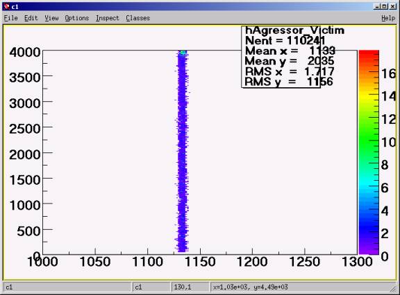
Draw("TDC17[20]:TDC17[16]
The left shift 13.5 ns is due to the cable length difference.
Run 12561. Combined crosstalk in the discriminator and the interlace-grounded cable
Aggressor: disk.01 -> cable.01 -> wire-> TDC17.20
Note. The grounding between the cable and the TDC is not as perfect as
in the
case when cable is plugged in directly.
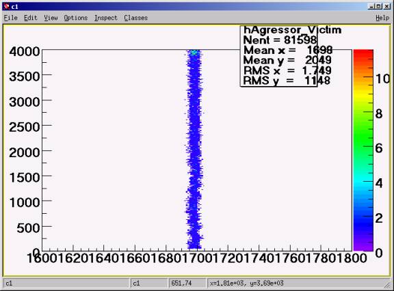
Draw("TDC17[20]:TDC17[16].
Combined crosstalk in the discriminator with the interlace-grounded cable is 25 ps.
Crosstalk is negligible, 25 ps.
Run 12561. Using standard cable.
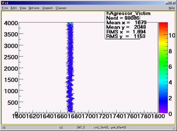
Combined crosstalk in the discriminator with the standard cable is 70 ps.
The left shift by 25 counts = 6 ns is due to the cable adapter cards.
Testing real cables from positive Padlles and Cherenkov
The discriminator moved to the tunnel.
The width of the discriminator pulse is 100 ns.
Run 12564. Standard cables. Crosstalk = 700 ps.
Victim: disc.00 -> standard cable -> TDC17[16]
Aggressor: disc.01 -> standard cable -> TDC17[17]
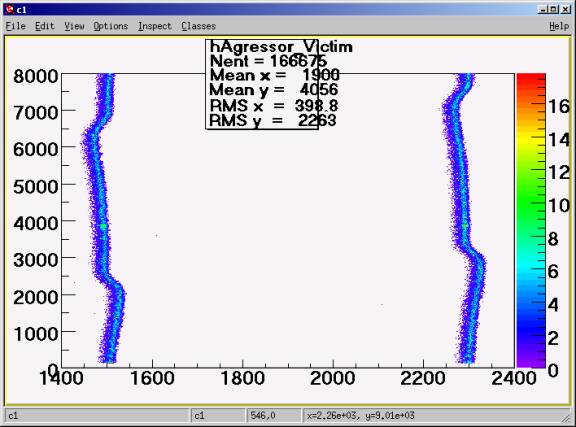
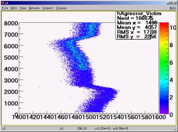
Draw("TDC17[17]:TDC17[16]
Crosstalk is 700 ps. Such data are un-analyzable.
Run 12566. Interlace-grounded cable. Crosstalk = 500 ps.
Victim: disc.00 -> standard cable -> TDC17[16]
Aggressor: disc.01 -> standard cable -> TDC17[17]
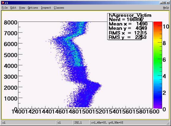
Draw("TDC17[17]:TDC17[16]
Crosstalk 500 ps.
Just slightly better than the standard cable.
Run 12569. Grounding on both ends. No effect.
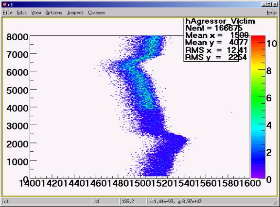
TDC17[17]:TDC17[16]
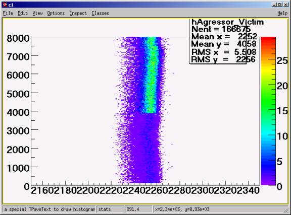
Draw("TDC17[17]:TDC17[24]
Even the neighbor # 8 is affected.
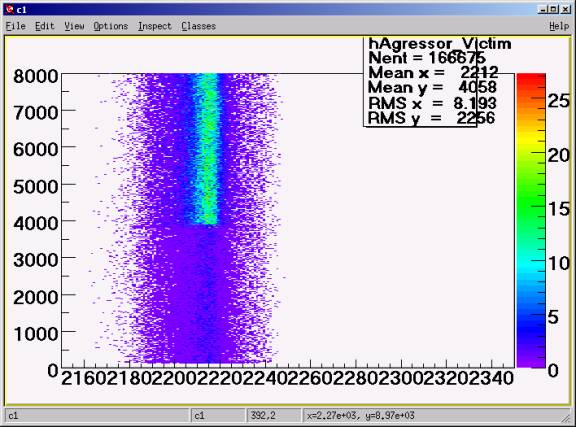
Draw("TDC17[17]:TDC17[31]
The neighbor #15 is not affected but it has a big RMS.
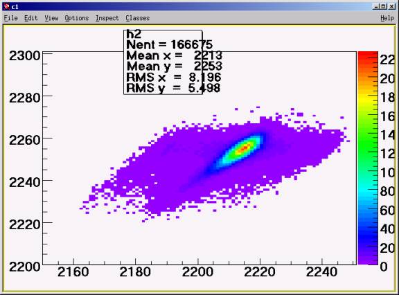
Draw("TDC17[24]:TDC17[31]
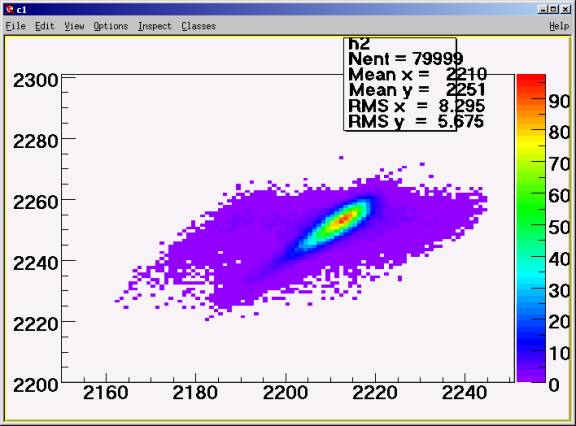
Draw("TDC17[24]:TDC17[31]>>h2","Revent<80000"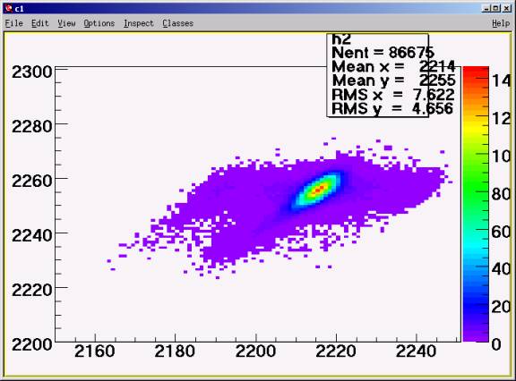
Draw("TDC17[24]:TDC17[31]>>h2","Revent>80000
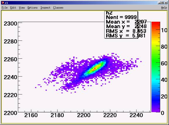
Draw("TDC17[24]:TDC17[31]>>h2","Revent<10000
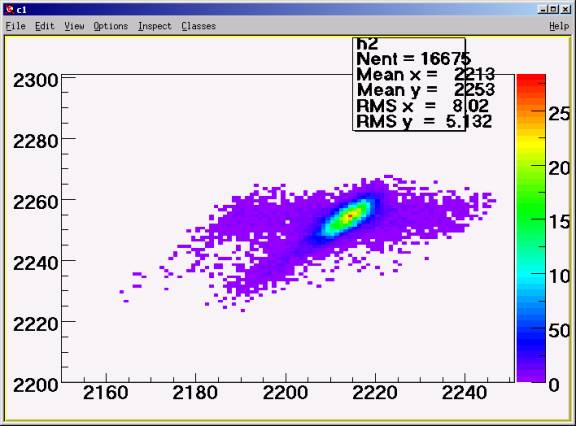
Draw("TDC17[24]:TDC17[31]>>h2","Revent>150000"
Run 12571. Next day. No aggressors.
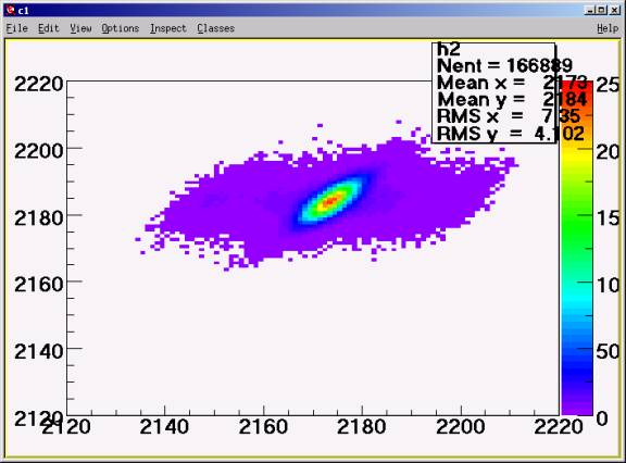
TDC17[24]:TDC17[31]
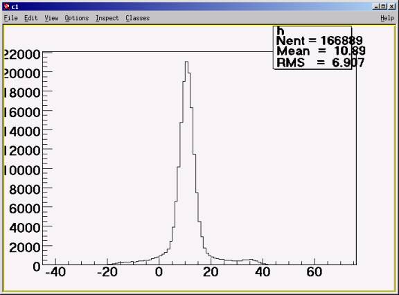
Draw("TDC17[24]-TDC17[31]
In the region 0:20 the RMS = 3.4
Run 12571,2. Effect of the grounding the cable in the tunnel.
Run 12571. Cable is grounded in the tunnel.
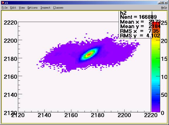
Draw("TDC17[24]:TDC17[31]
Run 12572. Cable is not grounded in the tunnel.
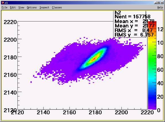
Draw("TDC17[24]:TDC17[31]
Things got worse for the pair 8.
Run 12753. Not grounded in the tunnel. The aggressor switched on.
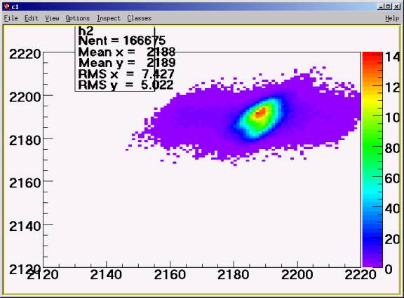
Drift disappeared. Something to do with the thermal stability?
Run 12573.
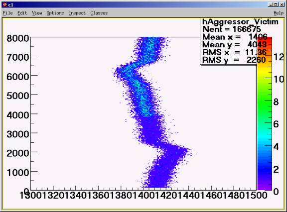
Draw("TDC17[17]:TDC17[16]
The RMS of the line itself = 7.
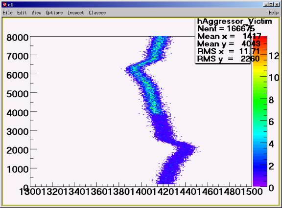
Draw("TDC17[17]:TDC17[16]-TDC17[24]+2200
The slow drift removed by using difference with channel 8.
The RMS of the line itself is 3.
Due to a slow drift during 13 minutes of the run the resolution changes from RMS=3 to RMS=7.
Run 12574.
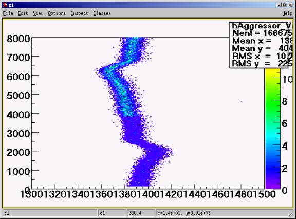
Draw("TDC17[17]:TDC17[16
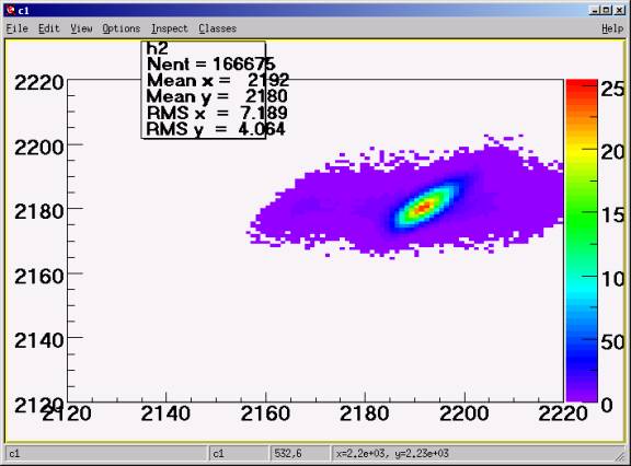
The picture did not change from run 12573. The grounding does not affect the drift.
Summary.
1. The crosstalk between the pairs of 3m long SpectraStrip cable with interlaced grounding is negligible.
2. The crosstalk at the existing cables is so big that it make impossible to analyze data in the presence of neighboring hits.
3. For long cables the interlace-grounded cable is only slightly better than the standard one. There is no sense to implement these cables.