T0 Study
Trouble: the RMS of the high-resolution peak is too big.
3/11/2003 Crosstalk study
FBRun 11466. 10000 events. T0 discriminator in slot 9.50 is masked out.
No counts in bin 950!
Conclusion:
By masking out single discriminator channel we are testing the chain from the output of the discriminator through the TEQ to TDC. No crosstalk found for channel 950
Trouble: the RMS of the high-resolution peak is too big.
|
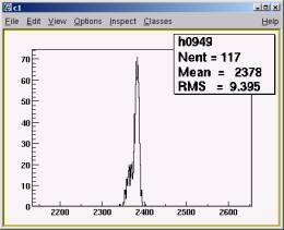
Fig
3031101 TC in high-resolution range, run 11466 |
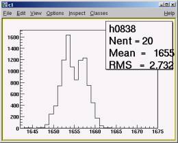
Let’s have a look at the L0. This is shows the jitter in L0 and the cable delay
Fig 3031102 L0 time, run 11466. 1 count = 100 ps This looks too wide, one could expect single bin distribution |
|
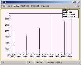
Fig
3031103 TDC8.37, Distance between peaks – 400 |
|
3/12/2003 L0 width study
|
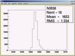
Fig
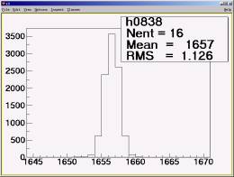
3031201. L0 for normal run 11468 The RMS is much better than for FBTIME run 11466 |
Fig
3031202. L0 for FBTIME run 10483 It is much better than FBTIME run 11466 but still wider than expected single bin distribution |
3/13/2003 L0 TDC fixed
It appeared that L0 was connected to the TDC not directly from the TML0 but after the gate delay generator, essentially it was the L0 output, which goes to TML1 board.
Fig
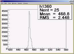
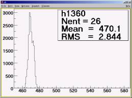
3031301. L0 for FBTIME run 11491.
1 Count = 25 ps. The clean TML0 output
delayed
96 ns using coaxial cable.
Crosstalk study continued
|
Run |
Date |
Channels |
Rate |
|
|
11499 |
03/13 17:34:59 |
T0P5 only |
~150 Hz |
0.01% errors in ADC[6] |
|
11521 |
03/14 12:41:18 |
T0P5 only |
~150 Hz |
0.01% errors in ADC[6] |
|
11523 |
03/14 12:49:14 |
All |
~ 50 kHz |
0.5% errors in ADC[6] |
|
11524 |
03/14 12:52:00 |
All |
~ 150 Hz |
0.01% errors in ADC[6] |
|
11530 |
03/14 17:04:29 |
All |
~150 Hz |
0.01% errors, |
|
11499 |
Fig
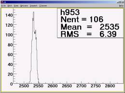
3031302. T0P5 for FBTIME run 11499. All |
|
|
11521 |
Fig
3031401. T0P.5 for FBTIME run 11521. |
Fig
3031402. L0 for FBTIME run 11521. |
|
11523 |
Fig
3031403. T0P.5 for FBTIME run 11523. |
Fig 3031404. L0 for FBTIME run 11523. |
|
11524 |
Fig
3031405. T0P.5 for FBTIME run 11524. |
Fig 3031406. L0 for FBTIME run 11524. |
|
|
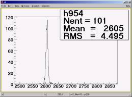
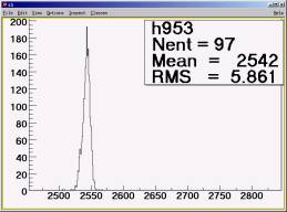
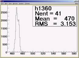
Fig 3031501. TOP5 for FBTIME run 11530, taken 5 hours after the run 11524. Drift =+17*25ps |
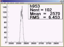
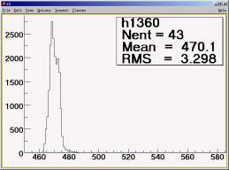
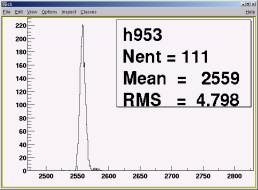
Fig 3031502. L0 for FBTIME run 11530, taken 5 hours after the run 11524. Drift = +7*25ps |

Summary:
1. The L0 in TDC13.60 does not shift at higher rates
2. The TDC13.60 drifted +7*25ps in 5 hours
3. The TOP5 shift due to high rate is not significant (~1 RMS)
4.
Single channel shifts by ~1 ns to lower times when all
channels fired.
5.
The rate of errors increased significantly with the
rate of applied triggers
Amplitude of the T0N9
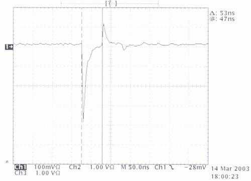
Fig.
3031407. Amplitude of the T0N9 from the cosmic. The second pulse is generated
on the
Y splitter connected by 25 ns cable. It bounced back (inverted) to PMT, there
it bounced back
again (non inverted) on PMT.
3/15/2003 Correlation between two coaxial cables
FBTIME run 11530.
L0TDC is standard signal: from L0 through coaxial cable 64+32 ns to TDC13.60
L0Dly is taken from the same, bridged L0 output through coaxial cable 90+16 ns to TDC13.61

|
11530 |
Fig
3031503. L0Dly for FBTIME run 11530, This signal is L0 delayed 90+16 ns. Compare
with fig. 3031502 where it was delayed by 64+32 ns |
Fig
3031504. L0Dly vs L0. |
|
|
Fig 3031503a. L0 |
Fig
3031503b. L0Dly-L0 |
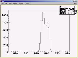
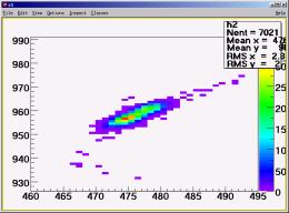
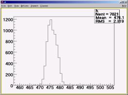
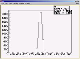
Note. In the time calibrator run the L0 pulse is wider than in normal run. This is due to TDC Discharge effect. In the TC runs for many channels the stop signals arrives before the start. This causes shifting to the left in all channels.
3/15/2003 Correlation between different TDC Channels for time calibrator pulses
|
11530 |
Fig
3031505. T0P1 vs T0P0. Same TDC |
Fig
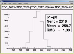
3031506. T0P1 - T0P0 |
|
|
Fig
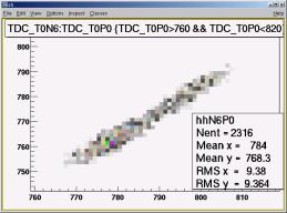
3031507. T0N6 vs T0P0. Different TDCs |
Fig
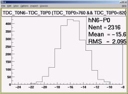
3031508. T0N6 - T0P0. Different TDCs |
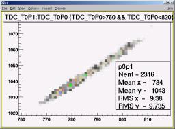
Summary:
- The difference between
two TDC channels of the same TDC for time calibrator pulse have RMS =
1.38*25 ps.
- The same difference but
for channels on different TDCs have RMS = 2.1*25ps.