Crosstalk in T0
|
|
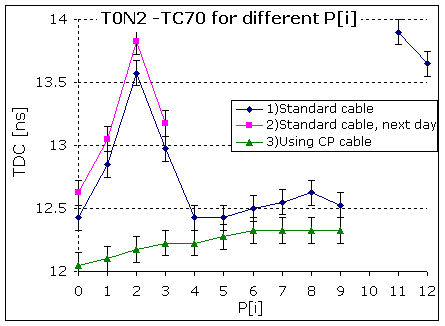
T0N2-TC70Difference between T0N channel 2 and TOF wall C channel 70
when different T0P channels are enabled. Two points on the right are special:
11 - when all channels are enabled, 12 – only T0P are enabled. By measuring
relative to TC70 we reduce the effect of slow drifts during the measurements. 3) – Using Cherenkov cable The most significant shift by ~1 ns in the T0N2 is seen
when signal is applied to T0P2. This effect is comparable to the case when
all channels enabled. There is no crosstalk between CherenkovP and T0N cables. |
|
|
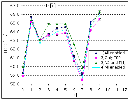
P[i]Absolute times of the T0P for the same measurements as in T0N2-TC70. In the case when we have one signal in T0N and one in T0P then the middle T0P lines get delayed by 1-2 ns relative to the case when all signals are fired. |
|
|
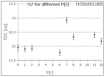
T0N7-TC70 The same as T0N2-TC70 but for the wire at the right edge of the cable and with different TDC. The two rightmost points are for ‘all enabled’ (11) and ‘T0P enabled’ (12) cases. Now the significant shift is when P7 is fired together
with N7. |
|
|
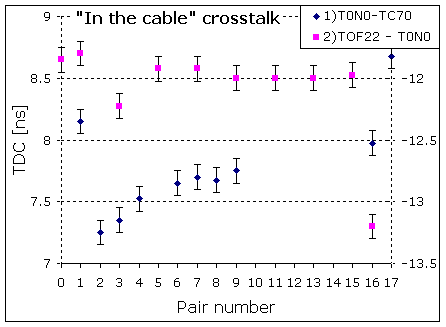
“In the cable” crosstalk. 1) Difference between pair 0 of T0N and TC70 2) Difference between pair 0 of TOF cable 22 and T0N. x=0: signal only in N0 x=1: signals in N0 and N1 x=2: signals in N0 and N2 … x=16: signals in all channels x=17: signals in all T0P channels. The nearest pairs have most influence. |
|
|
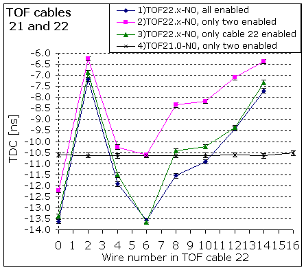
TOF cables 21 and 22. There is no crosstalk between TOF cables 21 and 22. They
probably are not close to each other. There is a crosstalk from adjacent cables to TOF22. |