Expert’s Guide to the TOF.
IV. Electronics
There are the four running modes (physics, cosmic, LED, and timing calibration) that require most of the same electronics but with variations. Each system other than the physics has a specific trigger and/or pulse generator that has to be routed into the event manager. The physics mode requires no trigger generated by the TOF wall. This trigger is generated by the trigger counters, and the TOF wall requires the least amount of electronics in this mode.
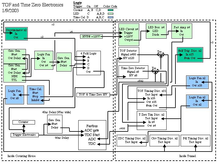
The base line electronics of the TOF for physics consists of a series of discriminators, ADC’s, TDC’s, and a high voltage supply. The gates for the ADC’s and TDC’s is generated using the trigger electronics and will not be discussed here. Any signal from the tube is split using a tee. From the tee, one end is sent through delay BNC cable directly into an ADC to measure energy deposited. The other end is sent into the discriminator that rests in a Camac crate below each wall. These discriminators are set at a common threshold and hold sixteen channels. The output of the discriminator is sent through a twisted pair ribbon cable into a TDC to measure the relative timing.
There is a sum output on the rear of these discriminators. This sum output will generate a –50mV NIM signal per channel fired. We can use this signal to trigger on the TOF itself for a cosmic run. Each discriminator used in normal physics mode, timing discriminators, has its sum output signal channeled into another discriminator, the trigger discriminator. We can set the threshold of this trigger discriminator such that we can accept so many PMT anodes firing per group of 8 scintillators. The sum output of the trigger discriminator is sent into another discriminator in the counting house. This discriminator has a threshold of about –30mV and will accept all signals from the trigger discriminator. The purpose of this discriminator is to make a good NIM signal for further logic. The signal from the final discriminator goes into a 4-fold logic unit, and from the logic unit, the signal is sent into the trigger electronics.
Another feature of the discriminator is that it has a test input, which fires all channels when there is a signal in the test input. We can use this feature for the TDC calibration and timing hardware tests. The signal is sent out to the discriminators through 2 fan out units, which put out 16 signals each. Each of these units is feed from a fan out unit that is in side the counting house with the signal originating from the stop of the timing calibration unit. The start is sent into the 4-fold logic unit mentioned above.
The timing calibration unit has two controls to it. You can choose a range of time over which you want to generate pulses. The period is the time between pulses. With this in mind, the range must be greater than the period. As an example, if the range is 10 microseconds and the period is 2 microseconds, then pulses will be generated at a relative zero, two microseconds after the zero, four microseconds after the zero, six, eight, and ten microseconds after the zero. The rate at which these pulses will fire is controlled using the rate knob at the bottom left of the module.
There is another pulse generating system in the same NIM bin as the timing calibrator. It is used for the LED gain monitoring system. The delay output of one gate generator is sent into the start of another, and the delay output of the later is sent into the start of the former. This loop generates standard NIM pulses, which can be varied in time by changing the width (delay) of the output signal. The loop is begun by pressing the trigger button on the gate generator. One of the gate generators puts out a NIM signal that is feed into a fan out. Four channels go into the tunnel to drive an LED circuit, while another goes into a gate generator to be properly delayed. These LED circuits require a pulsed signal and +120V DC. The voltage is supplied using two dual HV units, which are located in a NIM bin above the Lecroy HV mainframe. From the LED circuit, a signal is sent into an LED to strobe light into a bundle of optical fibers, which are routed to PMT’s. A pin diode is used to monitor variations of the LED light. Any signal from the pin diode is sent into a fast amp and then in to an ADC channel.
The PMT’s are supplied with at most +900V. This is controlled using the Lecroy 1458 High Voltage Mainframe. Each tube is connected to the supply voltage through a patch panel above each Camac crate.
For more information on the TOF electronics
Appendix in Erik's PhD Thesis on TOF Electronics