Expert’s Guide to the TOF.
II. Properties of the TOF
A. Scintillators.
The scintillators are made of BC404 plastic manufactured by Bicron cut to size and polished with a diamond drill bit to the size of 20cm x 8mm x 8mm. The characteristics of BC404 are such that its decay constant is 1.8ns and its moderate attenuation length is 1.6m. The wavelength of maximum emission is 408nm.
Aside from these manufacturer’s quotes on the properties of the scintillators, further studies of these scintillators resulted with more useful characteristics. The velocity of light inside the scintillator was determined to be 1.5x10^8 m/s. Each scintillator was tested to insure that the attenuation length of the cut scintillator slat was greater than 30cm.
The attenuation length is determined from using a well-collimated beta-source, Sr-90. A collimated beam of electrons was directed at a specific position on the scintillator. Using the energy ratio between the two signals from either PMT on each side, the slope of the ln of the energy ratios verses the position is the attenuation length. Each scintillator has an attenuation length greater than 30cm, as to assure that no more than 1/3 of the light isn’t lost in the wrapped.
The velocity of the light in the material is quoted as being 1.9x10^8 m/s. The measured value of 1.5x10^8 m/s is due to light that is generated in the scintillator having a random direction of propagation. Therefore, it will scatter through the scintillator, effectively increasing its path length, until it reaches a PMT. This path results in having a measured value less than the quoted but accurate enough for our purposes.
B. PMT
The PMTs used are Hamamatsu’s R5900-M4. The minimum effective area for the cathode of each tube is 18x18 mm^2. The tube is designed with 12 dynode stages between one cathode and a 2 x 2 segmented anode. The maximum supply voltage is +900V, and the tubes should never have a current greater than 400 microAmps. The tube is responsive to light with a wavelength of 300 to 650nm, and the wavelength of maximum response is 420nm. The tubes were ordered with a design specification that the current amplification (gain) for each anode was at least 2x10^6 or greater.
The gain was cross-checked at Rochester. This measurement only checked the average gain over the entire tube and not on each anode. By measuring the current over the cathode and similarly for the anodes in total, the gain can be easily calculated. The gain of each tube was measured to be greater than 2x10^6 with a supply voltage of +900V.


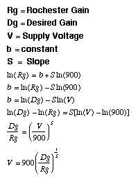
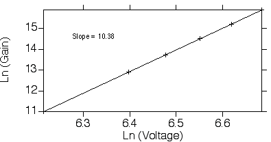
The gain of the tube is sensitive to the supply voltage. The ln of the gain is proportional to the ln of the supply voltage. The absolute gain of at a specific voltage is different from tube to tube. The rate of change in gain with respect to the rate of change in of the supply voltage is constant from tube to tube. The slope of a log-log plot of the gain verse the voltage is all we need to know to match the gain of the tubes by forcing them to all have the same gain at a specific voltage with respect to a reference tube. Any desired gain can be chosen over all the tubes with this information. A gain of 2.5x10^6 was chosen because this is the maximum gain of some tube due to the +900V supply voltage limit.
C. Detector
There are three properties of the detector unit as a whole that are important to know. This document will only list averages of these properties, yet the actual value can be looked up in any one of the TOF tables listing the specific characteristics from scintillator to scintillator. We are interested in the timing resolution, the position resolution, and cross-talk over the detector ending at the PMT.
The cross-talk was measured in each scintillator to ensure that no scintillator in a detector unit produced a cross-talk greater than 10%. This value refers to the amount of energy measured in neighboring channels when a signal was originated in a specific channel. The cross-talk was measured using a collimated electron source, Sr-90, directed at the center of a scintillator. The trigger was set such that all channels could generate a gate. Furthermore, cross-talk can occur in three places: between scintillators, between the light guides and the photo-cathode of the PMT, and between the cathode and the anode of the PMT. The later of these generates the most cross-talk. There should be minimal cross-talk from scintillator to scintillator because they are individually wrapped. The cross-talk between the light guide and the photo-cathode is small since the mounting fixture properly aligns the light guides to the face of the tube. Each scintillator used has at most 10% energy deposition measured in a neighboring channel as compared to the channel with real signal.

Using the timing information between both PMT’s on either end of a scintillator, the collision point of a particle with the scintillator can be determined to within a position resolution of 1cm. The position resolution was determined using a typical scintillator and finding the time difference measured between each PMT attached to the scintillator. The scintillator was illuminated using a well-collimated beam of electrons emitted by Sr-90 at a specific position along the scintillator. Once the linear relationship between the time difference and the position is understood, the velocity of light inside the cut scintillator can be found. The velocity was determined to be around 1.5x10^6m/s. With the timing resolution determined, our detectors can determine the vertical position of a hit in our sicntillators with a position resolution of 1cm.
The most important property of the TOF is the timing resolution. This characteristic was the most studied, and the final quality tests on the scintillators had to result in a timing resolution of 100ps or better. It is also known that the energy deposited is inversely proportional to the resolution. All preliminary quality assurance tests were done with Sr-90, a beta source. The amount of energy deposited from the electrons is at least half of that deposited from what is expected during the normal operation of RHIC. The resolution was found in a specified energy region through out the energy spectrum from the electron source. The relation between the resolution and the energy goes as one over the square root of the energy. As the energy increases, the resolution will decrease until an intrinsic resolution of the detector is reached. The average resolution of all the scintillators over a range of +/- 10% of the energy peak in the electron spectra is 80ps. This resolution was measured at Rochester, and this number will be effected by RHIC environment.