Expert’s Guide to the TOF.
I. Overview of TOF
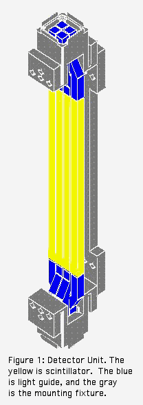
The Time of Flight wall is a scintillating plastic detector used primarily for particle identification. The wall’s current configuration consists of two sections with each section consisting of 120 scintillators. Each scintillator is made out of BC404 scintillating plastic with dimensions of 20cm x 8mm x 8mm. A group of four scintillators is coupled to 2 Hamamatsu PMTs via acrylic light guides. This results in 60 tubes per section, a total of 120 tubes in all. These pieces described above are glue together and held in unison with an aluminum frame termed as a mounting fixture, as seen in gray in figure 1. The mounting fixture is attached to the TOF support frame.


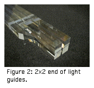
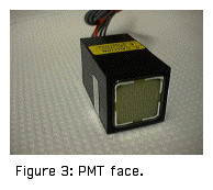
The light guides are designed to make sure that the path lengths from each scintillator to the PMT cathode are similar. Also, they had to match the 1x4 geometry of the scintillator, since they line up in a row, to the 2x2 geometry of the PMT. Figure 2 shows a group of four light guides used in matching to a PMT, as since in figure 3.
One of the sections rests inside the magnetic support structure. The magnetic field at the wall inside the support structure is approximately 100G. A study had to be done as to whether magnetic shielding was necessary. Preliminary tests show that the level of cross talk inside the tube increases dramatically. On either end of the detector unit, the PMT is covered with a magnetic shield, which attenuates the field enough that it will not have an effect on our tubes.
To eliminate cross talk of light from scintillator to scintillator, each scintillator is wrapped individually. A thin layer off aluminum foil is used with a layer of plastic tape protects the wrapping from being peeled off.
After the unit is all glued together, the unit is prepared for its final light tight wrap. This will protect the scintillators and PMT from exterior light. Black silicon paste is used to fill in all the gaps that light could enter and destroy the tube. The length of the scintillators is covered with a single wrap of Al foil, which extends up into the region between the mounting fixture and the light guide. The foil is not protected with a layer of tape and can be easily ripped off.

The wall and final light tight wrap is protected with a blue plastic shield attached to the support frame and the mounting fixtures. This shield can only protect the wall from light bumps and taps. It does not have the rigidity to protect the wall from heavy blows.

The TOF electronics are very simple and will be discussed later on. The basic idea behind the electronics is that each signal from the PMT is split. One signal goes into a charge integrating ADC to measure energy deposited, and the other goes through a discriminator then into a TDC. More electronics are used either to allow the TOF to trigger on itself or to run certain subsystems of the TOF.
The TOF has four running modes, which consist to two subsystems being implemented. There is the normal physics running mode, where the trigger is generated using a hit in a trigger counter and its necessary electronics. The cosmic run mode is a self-triggering method that is used to collect cosmic events for diagnostic purposes. For further diagnostic test, a pulse is applied to the test input for the timing discriminators. These events are used to understand the timing hardware for the TOF. The fourth running mode is used to monitor drifts in gain on the photo-tubes.
An LED pulser system is used to monitor this gain drift. This system consists of four LED’s driven by a circuit and +120V. Each LED is used to distribute light into one half of a section, or a quarter of the constructed wall to-date. The LED’s are housed in a box mounted on the rear of the wall section to the support frame. The light from the LED is directed to the middle of the photo-tube face using a fiber optic cable.