Not the final version!
Click here for the M$ version.
PHOBOS Cooling System
Operators Manual
By K.Oliwa, M.Stodulski,
February 2000
revised and updated version of that
written by W.Bogucki and translated by P.Decowski
November 1999
Table of Contents
1. Introduction 3
1.1 Basic Functionality 3
1.2 Construction 3
1.3 Principle of Operation 8
1.4 Control System and Emergency Procedures 9
1.5 Monitoring Signals (Slow Control) 12
2. Cooling System operation 15
2.1 Before turn-on 15
2.2 Filling up and emptying the cooling system 15
2.3 System Turn-on 16
2.4 Normal operation 16
2.5 Operation with bigger leakage 16
2.6 Emergency operation 16
2.7 Automatic pump down of the system……………………………….. ……………16
2.8 Manual pump down of the system…………………………………………………17
2.9 Remote pimp down and turn off the system………………………………………17
2.10 Coolant removal from a number of cooling elements…………………………….18
2.11 Roll out the detectors…………………………………………………………….18
2.12 Chiller Turn-on…………………………………………………………………..19
2.13 System Turn-off 20
2.14 Maintenance 20
2.14.1 Coolant refill………………………………………………………………… ..20
2.14.2 Inspection of water filers……………………………………………………….21
3. Appendix 22
3.1 Water cooling system diagram 22
3.2 Cooling system -Automatic control diagram 22
3.3 Cooling system slow control -analog part 22
3.4 Cooling system slow control -digital part 22
The cooling system is designed to cool silicon detector electronics and special thermal-shields that thermally separate the electronics from magnet poles in the PHOBOS experiment. Distilled water with additives is used as the coolant. A special, under-pressure cooling system is used to prevent flooding of the electronics in case of coolant leakage. The system is designed for continuous operation when the circuitry is leak free or there is a small leakage. If a big leakage occurs, then the system should first automatically try to prevent spillage by turning on an additional vacuum pump. If this is not enough, then an automatic procedure to empty the circuitry is started, thus preventing flooding and damage to the detectors and electronics.
1.2 Construction
The cooling system consists of two separate circuitry’s. First circuit it is a chiller connected with hoses of 1" ID to a heat exchanger mounted in the cooling system rack. The second circuit includes the rack itself, a manifold mounted on the magnet, an upper tank, four thermal shields and three detectors. The rack is connected with hoses of 1 ¼" ID to the manifold. The thermal shields are connected with hoses of 5/8" ID to the manifold while the detectors with hoses of ½" ID. The upper tank is connected also with hoses of ½" to the manifold and the rack as well.
Chiller
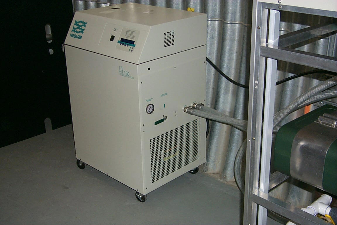
An air-cooled HX-150 chiller of NESLAB Company has been chosen, Fig.1. Cooling capacity of the chiller is 4.5 kW at ambient temperature of 20 ° C. The chiller allows to set coolant temperature within the range 5-35 ° C with accuracy of ± 0.1 ° C. User’s manual of the chiller is supplied.
Fig.1 HX-150 chiller of NESLAB Company
Cooling system rack
The rack is a mechanical support structure made of PA38 aluminum alloy frame and aluminum cover sheets painted black and "computer". Inside the rack there are following components:
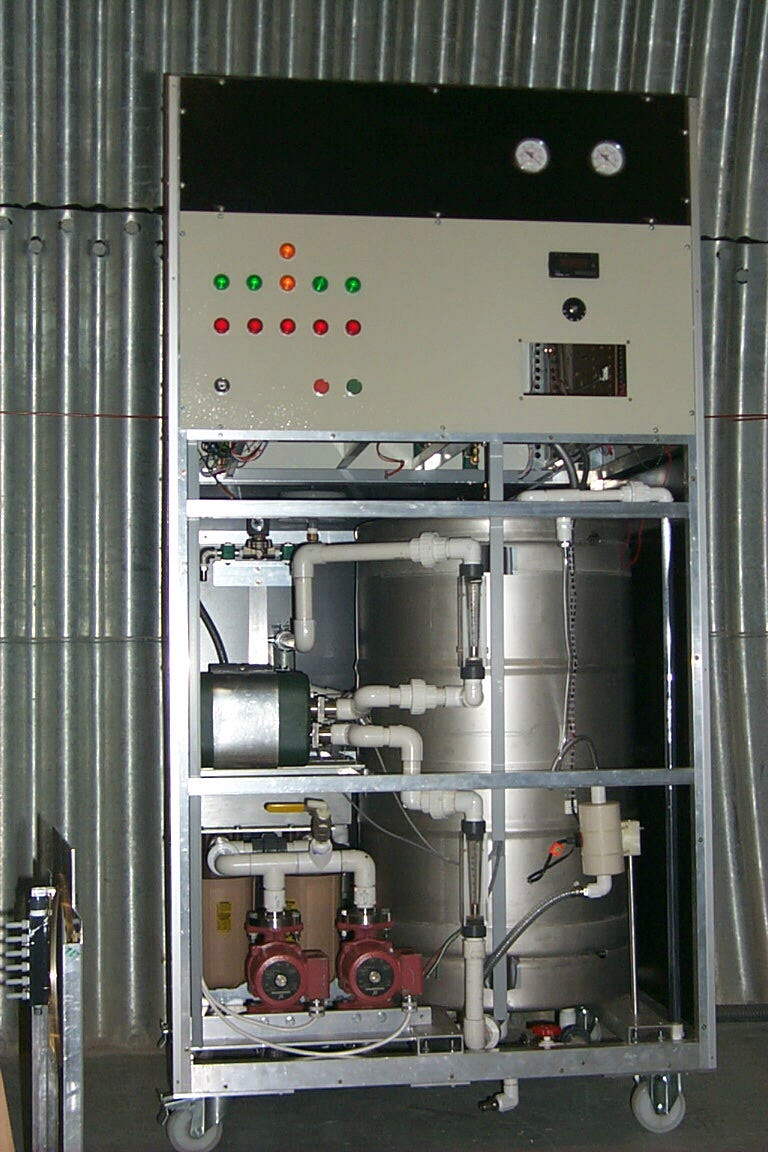
Fig.2 Cooling system rack (some covers removed)
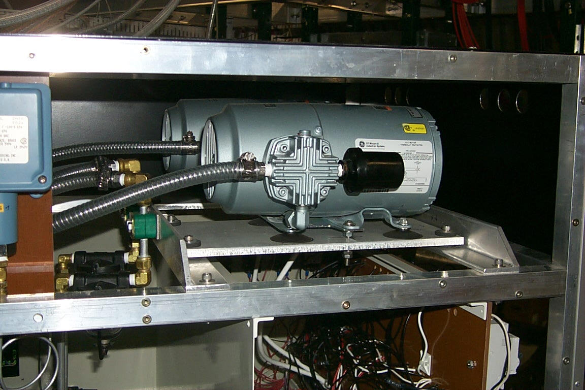
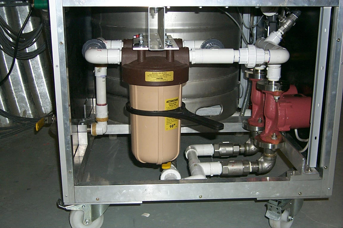
Fig.3 Water and vacuum pumps (side and back view of the rack)
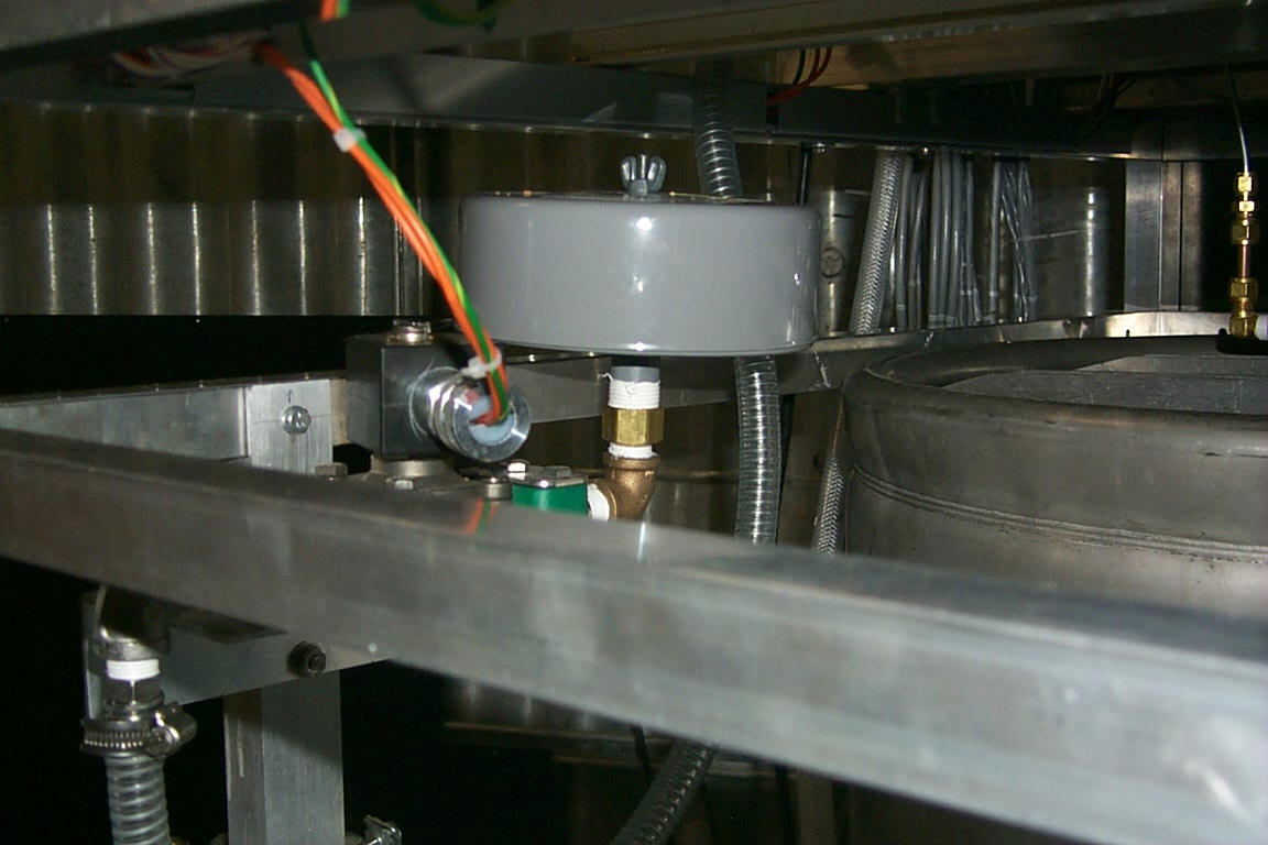
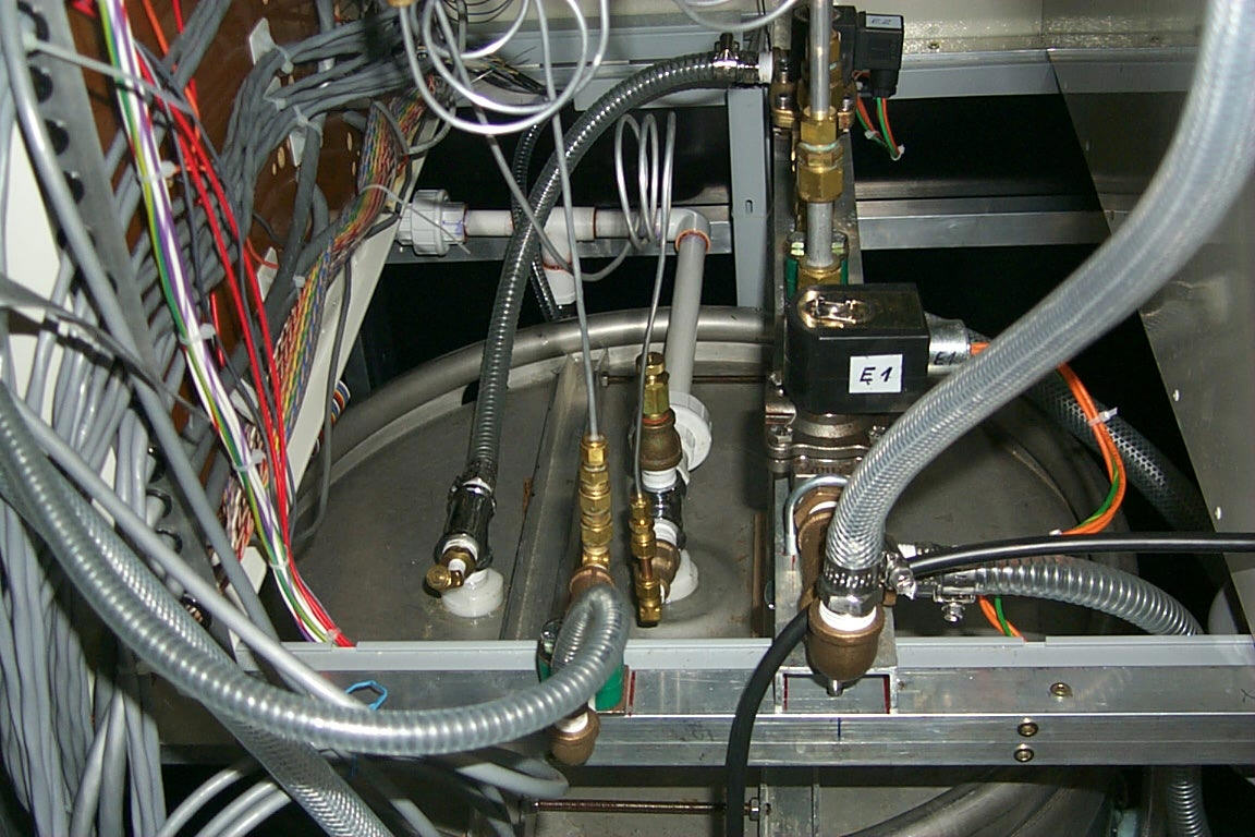
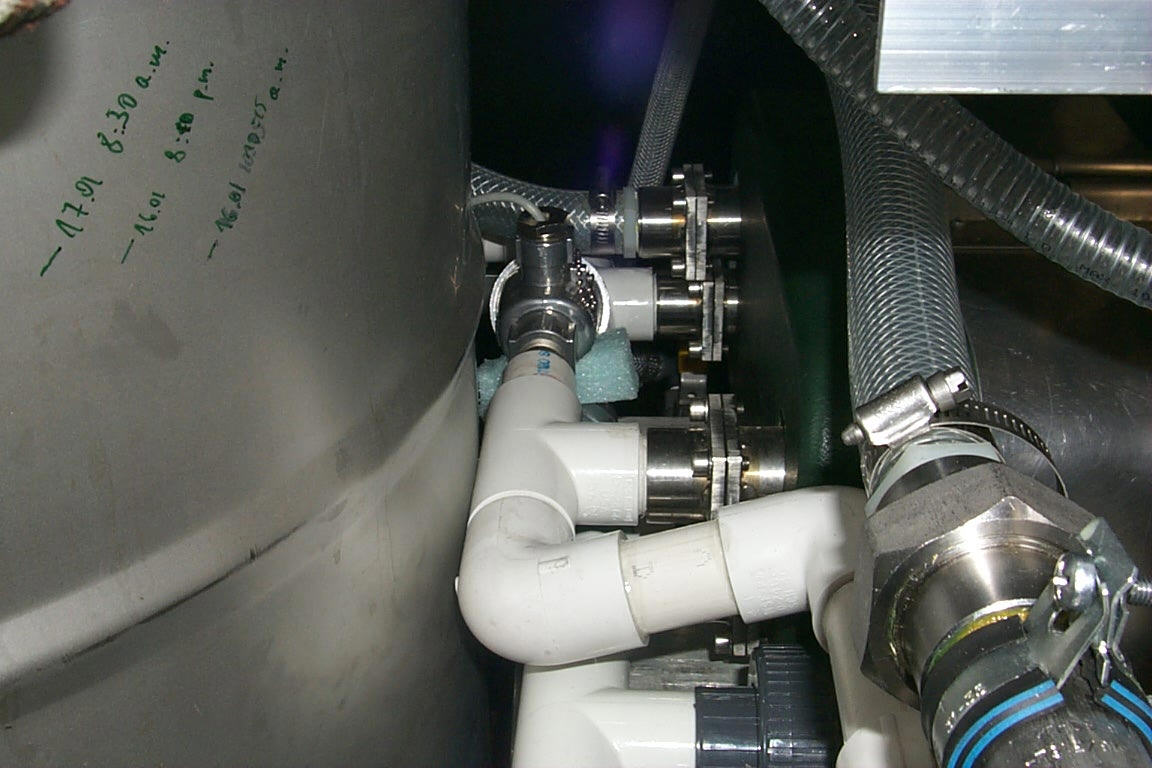
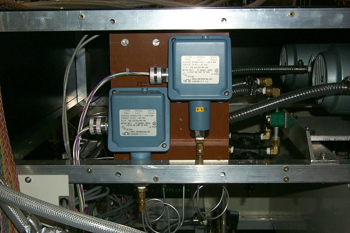
Fig.4 Control and measurement devices
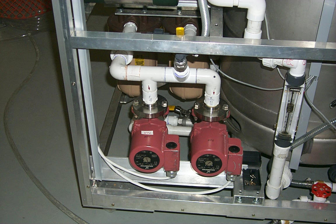
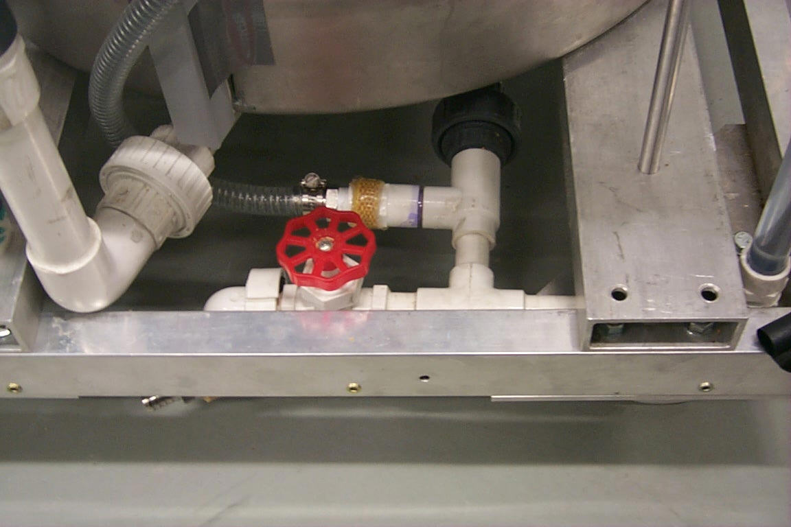
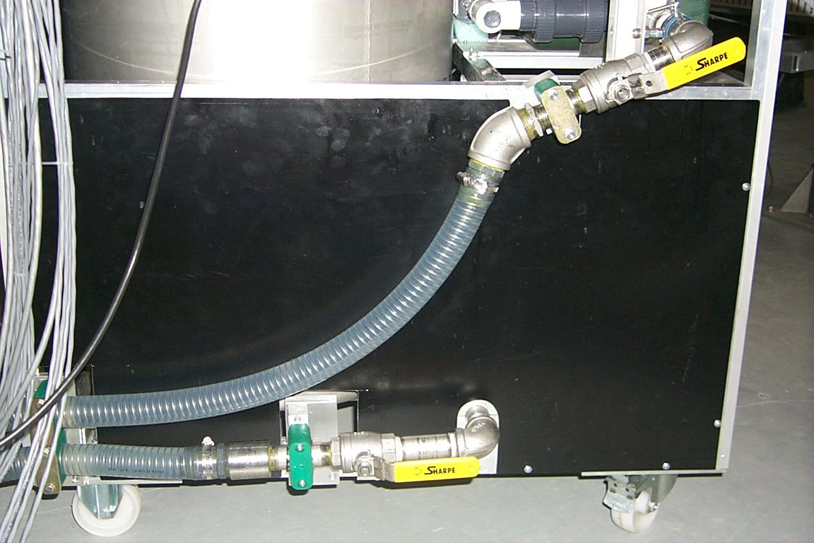
Fig.5 Valves in the rack (front view-upper, back view-lower)
Manifold on the magnet
The manifold on the magnet is built out of 1 ¼" and ½" ID plastic pipes fastened to the magnet with clamps. The manifold consist of, Fig.6, 7:
Detectors
There are eight cooling frames in each spectrometer arm and six sets of cooling pipes in the octagon frame. The cooling frames and pipes are connected to their distributors and collectors with plastic tubing of ¼" ID. The distributors are also coolant flow indicators. The cooling frames/tubes, the flow indicators and the collectors are mounted on sliding bases of the spectrometer arms and of the octagon. Quick-disconnect couplings are applied to easy dismount of each detector. If any detector is dismounted its flow indicator and collector should be short connected with plastic tubing
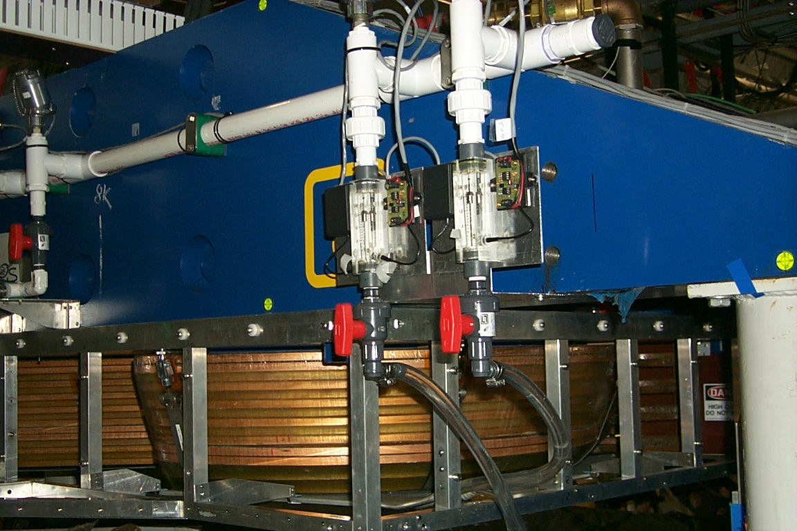
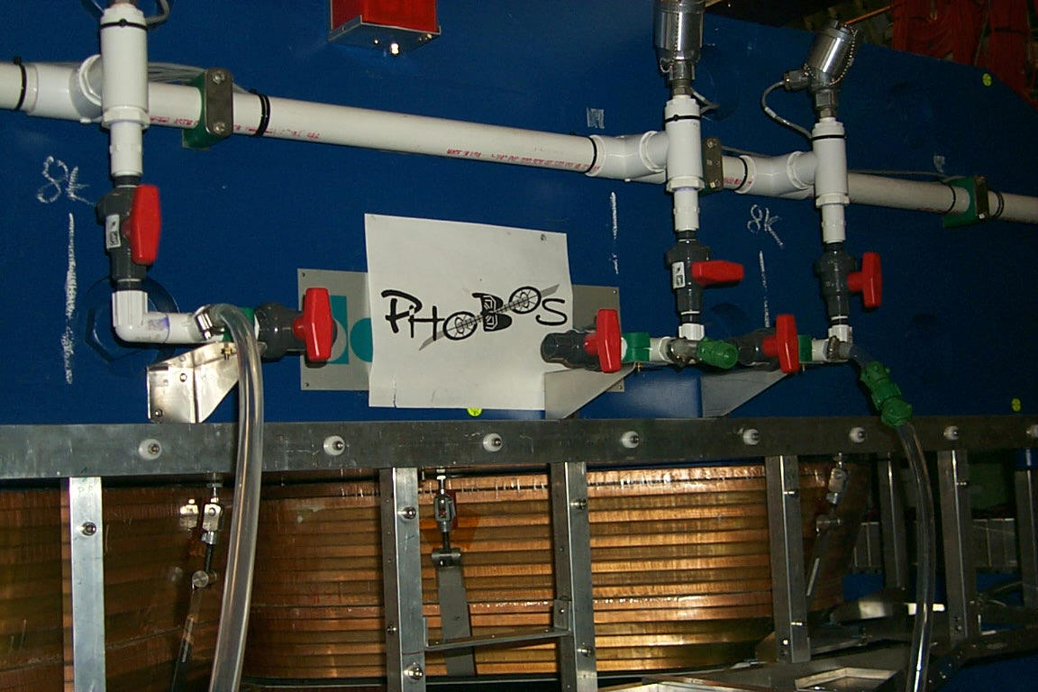
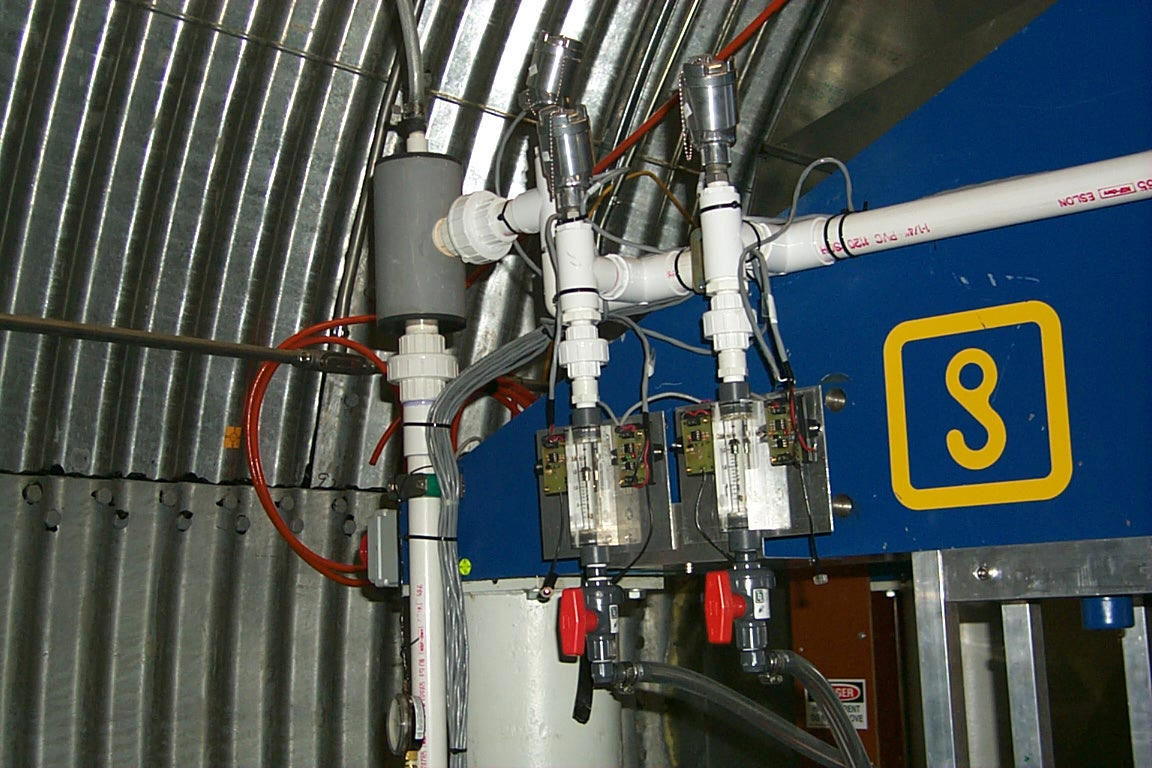
Fig.6 Main collector with thermometers, valves and flow meters (from left - outer thermal shields, detectors and inner thermal shields)
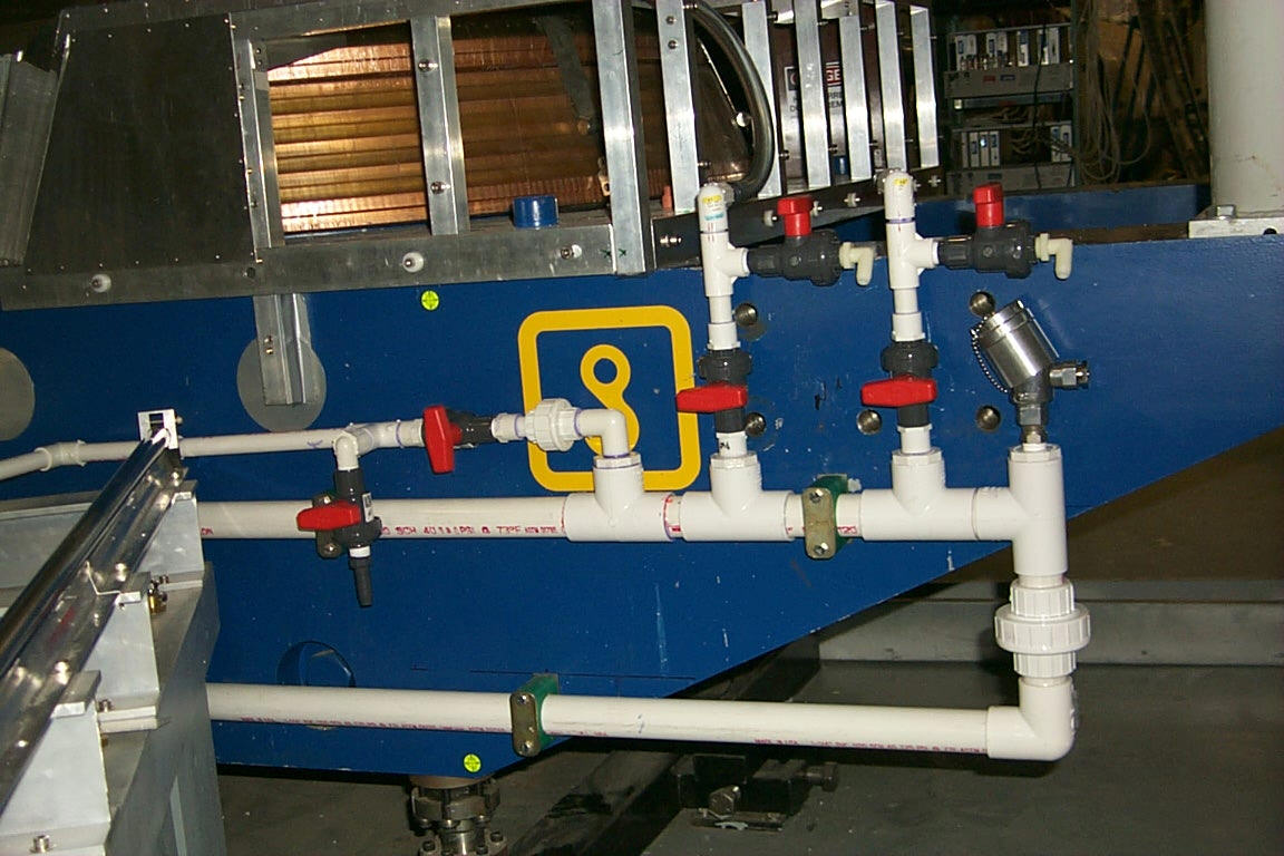
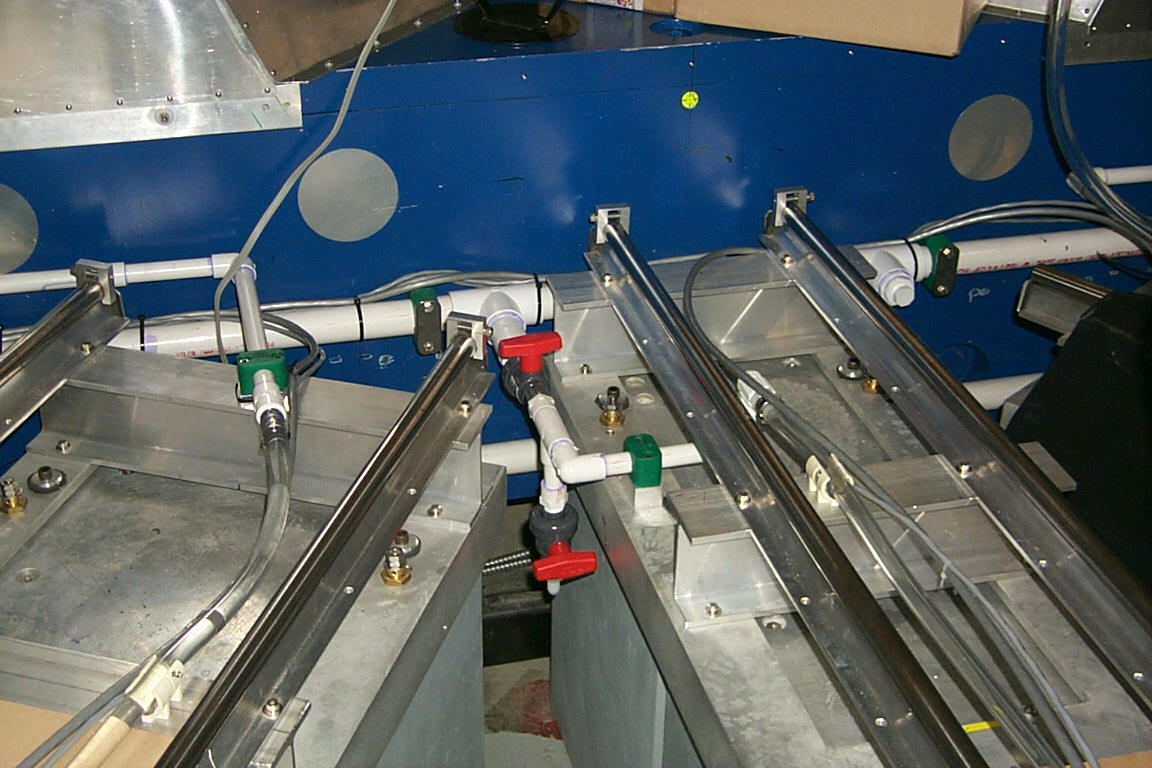
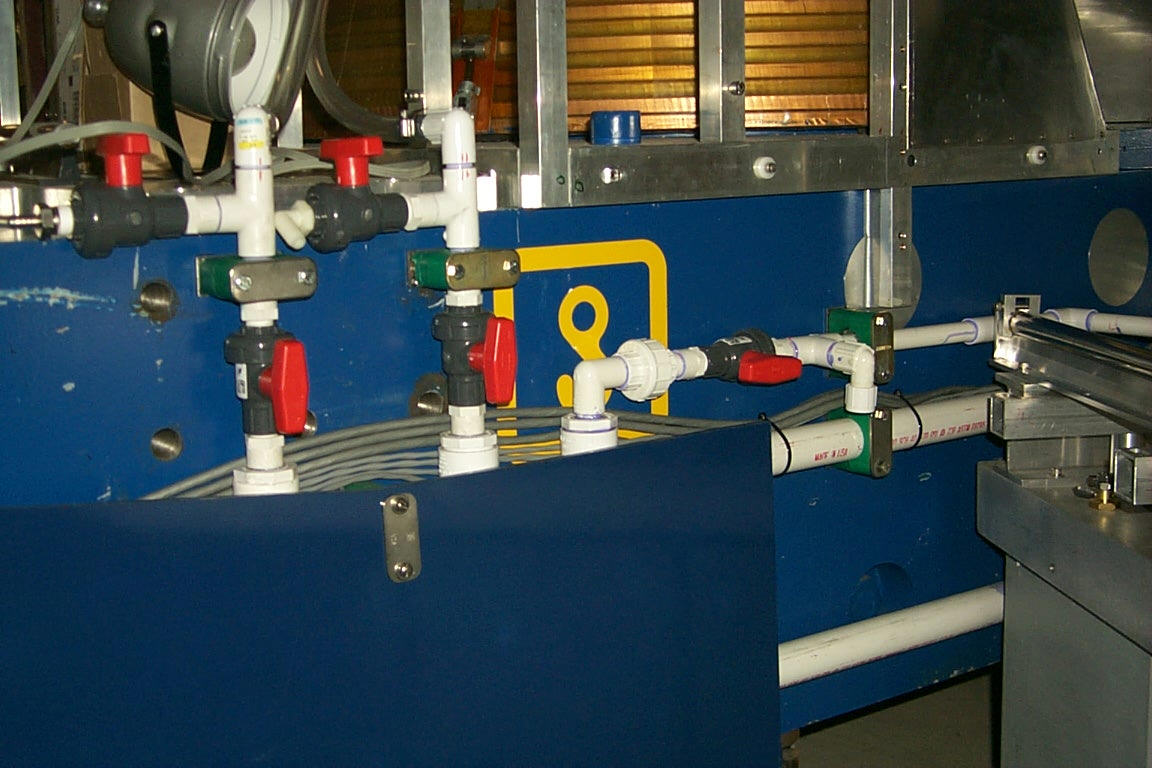
Fig.7 Main distributor with valves and thermometer (from left – outer, central and inner part)
prepared. That allows keeping similar terms while the system ran. In turn, the flow indicator and the collectors are connected to the manifold with hoses of ½" ID. Each detector has two valves enabling shut off coolant flow through it and one valve on return side enabling air intake to empty the detector.
Thermal shields
There are four aluminum thermal shields made by a company DATE in France. They are mounted on each magnet pole tip, however, there is 1 mm air gap between the shields and the pole tips. Manifolds of the thermal shields are supported / suspended from a detector enclosure frame. Each thermal shield has two valves enabling shut off coolant flow through it and one valve on supply side enabling air intake to empty the shield. The thermal shields are connected to the manifold on the magnet with hoses of 5/8" ID, Fig.6, 7.
Upper tank
The upper tank, Fig.8, is connected to the air separator and the vacuum pumps with hoses of ½" ID. There is a third hose of smaller diameter connected to a pressure sensor controlling the vacuum pumps through the switch PS1. A liquid level switch SF2 is built in the upper tank to protect the vacuum pumps against accidental intake of the coolant. The switch turns the pumps off if the coolant comes too high. In that case red light L2 on the front panel is on.
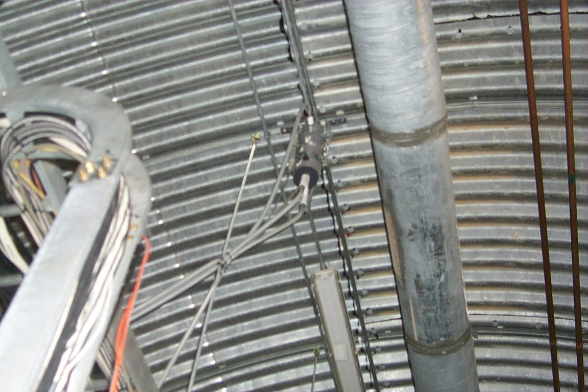
Fig.8 Upper tank
The system operates in under-pressure, which prevents water from spilling out in case there is a leak. However, during a leak outside air will enter the system and gradually raise the internal pressure. A vacuum pump is used to maintain the correct inside under-pressure in the system. The pump is automatically turned on and off by pressure switch PS1. The vacuum pump is turned off when the required under pressure is achieved. At the same time the water pump WP2 is turned on, pumping water through the cooling elements. Since the cooled elements (electronics) are connected to the intake side of the coolant pump, an additional reduction in pressure is attained through the water flow resistance. This causes a reduction in the water column height above the air separator, which in turn can cause a water/air mixture intake by the water pump. In principle, such a mixture will worsen the effectiveness of the water pump and will shorten its lifetime. However, it seems not to be danger in our system due to low working pressure of the water pumps. Maximum pressure difference is smaller than 1 bar. A chiller and a heat exchanger maintain coolant temperature.
The figure below shows the front panel with the control and emergency indicators of the system.
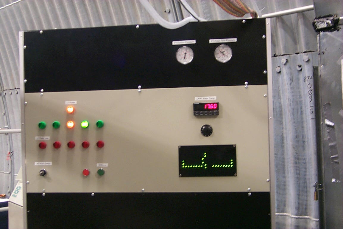
Fig.9 Front panel of the cooling system rack
Switches
MS – Switch with key enabling controlled mode of the rack (the key turned to the right)
BT1 - Button to pump down the system; button needs to be depressed by about 5 seconds (RT4)
to initiate the procedure
BT2 - Cancel pump down the system; the system will go back to normal operating mode
Pressure gauges and sensors (work always)
P1 – Pressure measured in the upper tank; the gauge on the front panel shows negative pressure during system operation while the sensor used for monitoring measures absolute value
P2 – Pressure measured in the coolant tank; the gauge on the front panel shows negative pressure during pump down the system while the sensor used for monitoring measures absolute value; always except pump down procedure the sensor measures ambient pressure in the hall
Temperature display (requires controlled mode of the system)
DP20 – Programmable display for reading out temperature of the coolant
RS – Rotary switch allowing for sequential read out of tw1-tw11 thermometers (PT100)
Status indicators are on while (require power supply and/or controlled mode):
L1 – The rack is plugged in
L2 - Coolant level in the tank is too low. Operation is not possible
L3 – The rack is in controlled mode
L4 - Main vacuum pump VP1 is on
L5 - Reserve vacuum pump VP2 is on
L6 - Main water pump WP1 is on
L7 - Reserve water pump WP2 is on
L8 - Water is in the upper tank
L9 – Vacuum pump starts suction of the tank
L10 - Valve E3 is on (air is being let into the top tank)
L11 – Pump down procedure starts; coolant is being removed from the detectors and thermal shields
as well and pumped to the tank
L12 – There is normal coolant flow through each cooling frame of the: inner spectrometer arm (ISA#1…ISA#8), octagon (OCT#1…OCT#6), outer spectrometer arm (OSA#!…OSA#8) and through each thermal shield: inner upper (IUTS), inner lower (ILTS), outer upper (OUTS), outer lower (OLTS), Fig.10.
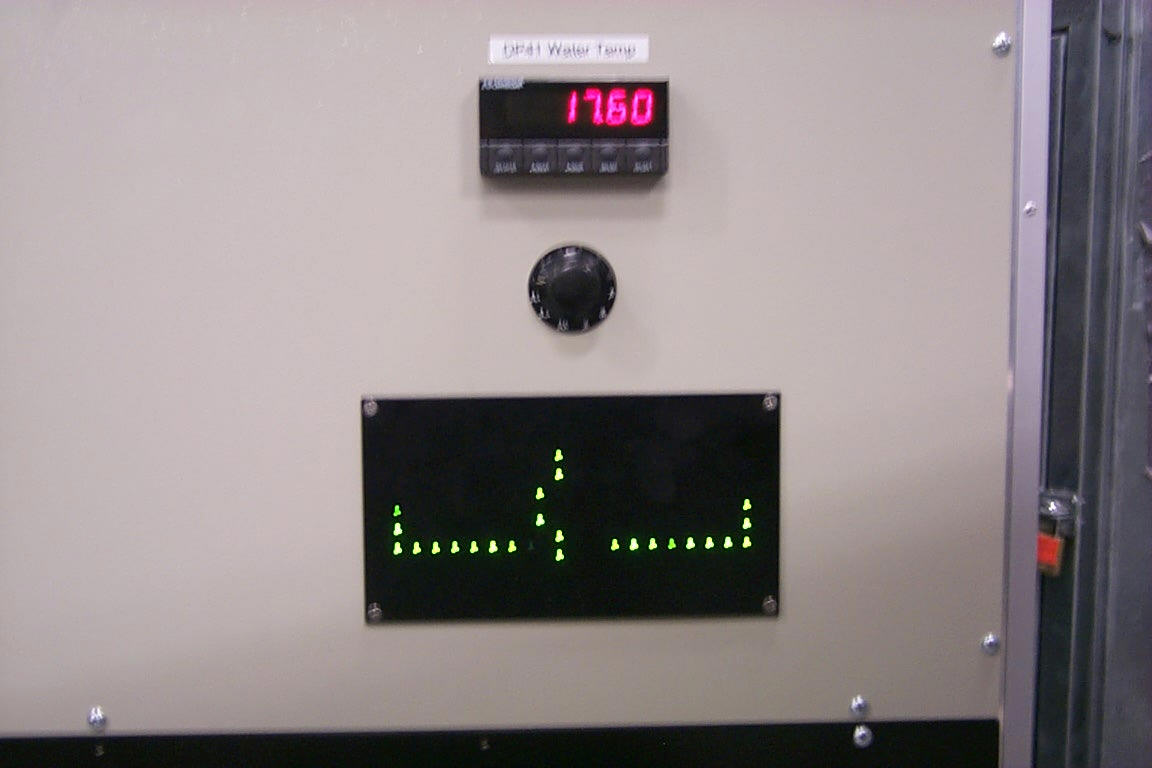
Fig.10 Indication of coolant flows through each cooling frame and each thermal shield
The control system enables the following functionality:
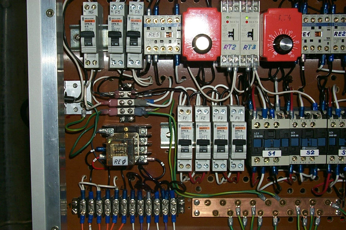
Fig.11 Fuses MF, F1-F6 and time relays RT1-RT4 in the cooling system rack
Cooling system rack - Specification of the analog signal points
|
Point symbol |
Description |
Output |
Range |
Equation |
|
|
1 |
tw1 |
Chiller supply water temperature |
1 to 5Vdc |
-17.8 to 93,3°C |
T=27.775*U- 45.575 ( t[°C], U[V] ) |
|
2 |
tw2 |
Cooling rack return water temperature |
1 to 5Vdc |
-17.8 to 93,3°C |
|
|
3 |
tw3 |
Main distributor supply water temperature (on the magnet) |
1 to 5Vdc |
-17.8 to 93,3°C |
|
|
3 |
tw4 |
Inner upper thermal shield return water temperature |
1 to 5Vdc |
-17.8 to 93,3°C |
|
|
5 |
tw5 |
Inner bottom thermal shield return water temperature |
1 to 5Vdc |
-17.8 to 93,3°C |
|
|
6 |
tw6 |
Inner spectrometer arm return water temperature |
1 to 5Vdc |
-17.8 to 93,3°C |
|
|
7 |
tw7 |
Octagon return water temperature |
1 to 5Vdc |
-17.8 to 93,3°C |
|
|
8 |
tw8 |
Outer spectrometer arm return water temperature |
1 to 5Vdc |
-17.8 to 93,3°C |
|
|
9 |
tw9 |
Outer lower thermal shield return water temperature |
1 to 5Vdc |
-17.8 to 93,3°C |
|
|
10 |
tw10 |
Outer upper thermal shield return water temperature |
1 to 5Vdc |
-17.8 to 93,3°C |
|
|
11 |
tw11 |
Main collector return water temperature |
1 to 5Vdc |
-17.8 to 93,3°C |
|
|
12 |
ap1 |
Absolute pressure in the system |
1 to 5Vdc |
0 to 100kPa |
equation |
|
13 |
ap2 |
Absolute pressure in the main water tank |
1 to 5Vdc |
0 to 100kPa |
equation |
Cooling system rack - Specification of the digital signal points
|
Point symbol |
Description |
Output |
Range |
||
|
1 |
wf1-I |
water flow in the inner spectrometer arm frame F1-I, ISA#1 |
ON OFF |
0Vdc ± 0,5V 5Vdc + 0,5V |
|
|
2 |
wf2-I |
water flow in the inner spectrometer arm frame F2-I, ISA#2 |
ON OFF |
0Vdc ± 0,5V 5Vdc + 0,5V |
|
|
3 |
wf3-I |
water flow in the inner spectrometer arm frame F3-I, ISA#3 |
ON OFF |
0Vdc ± 0,5V 5Vdc + 0,5V |
|
|
3 |
wf4-I |
water flow in the inner spectrometer arm frame F4-I, ISA#4 |
ON OFF |
0Vdc ± 0,5V 5Vdc + 0,5V |
|
|
5 |
wf5-I |
water flow in the inner spectrometer arm frame F5-I, ISA#5 |
ON OFF |
0Vdc ± 0,5V 5Vdc + 0,5V |
|
|
6 |
wf6-I |
water flow in the inner spectrometer arm frame F6-I, ISA#6 |
ON OFF |
0Vdc ± 0,5V 5Vdc + 0,5V |
|
|
7 |
wf7-I |
water flow in the inner spectrometer arm frame F7-I, ISA#7 |
ON OFF |
0Vdc ± 0,5V 5Vdc + 0,5V |
|
|
8 |
wf8-I |
water flow in the inner spectrometer arm frame F8-I, ISA#8 |
ON OFF |
0Vdc ± 0,5V 5Vdc + 0,5V |
|
|
9 |
wf1-oct |
water flow in the octagon circuit 1, OCT#1 |
ON OFF |
0Vdc ± 0,5V 5Vdc + 0,5V |
|
|
10 |
wf2-oct |
water flow in the octagon circuit 2, OCT#2 |
ON OFF |
0Vdc ± 0,5V 5Vdc + 0,5V |
|
|
11 |
wf3-oct |
water flow in the octagon circuit 3, OCT#3 |
ON OFF |
0Vdc ± 0,5V 5Vdc + 0,5V |
|
|
12 |
wf4-oct |
water flow in the octagon circuit 4, OCT#4 |
ON OFF |
0Vdc ± 0,5V 5Vdc + 0,5V |
|
|
13 |
wf5-oct |
water flow in the octagon circuit 5, OCT#5 |
ON OFF |
0Vdc ± 0,5V 5Vdc + 0,5V |
|
|
14 |
wf6-oct |
water flow in the octagon circuit 6, OCT#6 |
ON OFF |
0Vdc ± 0,5V 5Vdc + 0,5V |
|
|
15 |
wf1-O |
water flow in the outer spectrometer arm frame F1-O, OSA#1 |
ON OFF |
0Vdc ± 0,5V 5Vdc + 0,5V |
|
|
15 |
wf2-O |
water flow in the outer spectrometer arm frame F2-O, OSA#2 |
ON OFF |
0Vdc ± 0,5V 5Vdc + 0,5V |
|
|
17 |
wf3-O |
water flow in the outer spectrometer arm frame F3-O, OSA#3 |
ON OFF |
0Vdc ± 0,5V 5Vdc + 0,5V |
|
|
18 |
wf4-O |
water flow in the outer spectrometer arm frame F4-O, OSA#4 |
ON OFF |
0Vdc ± 0,5V 5Vdc + 0,5V |
|
|
19 |
wf5-O |
water flow in the outer spectrometer arm frame F5-O, OSA#5 |
ON OFF |
0Vdc ± 0,5V 5Vdc + 0,5V |
|
|
20 |
wf6-O |
water flow in the outer spectrometer arm frame F6-O, OSA#6 |
ON OFF |
0Vdc ± 0,5V 5Vdc + 0,5V |
|
|
21 |
wf7-O |
water flow in the outer spectrometer arm frame F7-O, OSA#7 |
ON OFF |
0Vdc ± 0,5V 5Vdc + 0,5V |
|
|
22 |
wf8-O |
water flow in the outer spectrometer arm frame F8-O, OSA#8 |
ON OFF |
0Vdc ± 0,5V 5Vdc + 0,5V |
|
|
23 |
ThS1 |
Water flow in the outer upper thermal shield |
ON OFF |
0Vdc ± 0,5V 5Vdc + 0,5V |
|
|
24 |
ThS2 |
Water flow in the outer lower thermal shield |
ON OFF |
0Vdc ± 0,5V 5Vdc + 0,5V |
|
|
25 |
ThS3 |
Water flow in the inner lower thermal shield |
ON OFF |
0Vdc ± 0,5V 5Vdc + 0,5V |
|
|
26 |
ThS4 |
Water flow in the inner upper thermal shield |
ON OFF |
0Vdc ± 0,5V 5Vdc + 0,5V |
|
|
27 |
DS1 |
Main vacuum pump (VP1 ) |
ON OFF |
0Vdc ± 0,5V 5Vdc + 0,5V |
|
|
28 |
DS2 |
Reserve water pump (WP1) |
ON OFF |
0Vdc ± 0,5V 5Vdc + 0,5V |
|
|
29 |
DS3 |
Coolant level in the tank too low |
Alarm O.K. |
0Vdc ± 0,5V 5Vdc + 0,5V |
|
|
30 |
DS4 |
Water in the upper tank |
Alarm O.K. |
0Vdc ± 0,5V 5Vdc + 0,5V |
|
|
31 |
DS5 |
Start pump down procedure |
Alarm O.K. |
0Vdc ± 0,5V 5Vdc + 0,5V |
2. Cooling System operation
The following checks need to be performed before turn on:
Capacity of the tank in the cooling system rack is about 55 gallons. It is suggested to fill up the tank with 40 gallons of coolant (MAX). 30 gallons of the coolant remain in the tank during operation of the cooling system (NOR). The minimum water level regulator is already adjusted at a height corresponding to 14 gallons of the coolant (MIN). If coolant level reaches minimum (L2 on) the system either cannot be started up or stops operating. Three coolant levels MAX, NOR, MIN corresponding to these three numbers are marked at a coolant level indicator and the frame of the
rack.
Fig.12 Front view of the cooling rack (some cover sheets removed)
The tank may only be filled with distilled water with some additives, to limit bacterial and algae growth. The additives are not determined yet. Chloramine – T used in the NESLAB chiller circuitry is not recommended because it can affect aluminum pieces and cast iron body of the water pumps (Robert Pak takes care of looking for proper additives). The coolant stored in external containers of 40 gallons total capacity can be pumped into the tank by means of an electrical pump. The pump is connected with a hose of ½" ID to the valve V0. During filling up the valve V1 should be closed. The same equipment is necessary for emptying the tank. However, the valve V1 should be open in
that case. The containers and the electric pump are to be procured.
The system can be turned on after the preliminary inspection (see 2.1). To enable the system, turn the key in the main switch MS to the right. The vacuum pump should turn on first and after a few minutes, the water pump. If the water in the system has previously been removed, then the turn-on should happen in stages. Turn on switch MS, wait 10-20s, turn it off and wait for a few minutes. Then turn switch MS back on for 10-20s. This should be repeated a number of times, until the system is free of any trapped air. The water pump turns on automatically when the vacuum pump shuts down. Observe the lower flow meter when this happens, Fig.12 . There should be a 10 Gpm flow in normal operation.
The main water pump (WP2) is functioning continuously during normal operation. When there is slight leakage, the vacuum pump operates only occasionally. Negative pressures in the top and in the coolant tanks are about – 0.5 bar and 0 bar respectively. There is no coolant above the separator. L1, L3, L6 are continuously on and L4 only occasionally. All lights on L12 should be on. Thermometer tw1 should indicate the same or very close temperature to that preset in the chiller.
Similarly to the normal operation but the main vacuum pump turns on more frequently.
The leakage is so big the main vacuum pump is continuously on. After 30 seconds the reserve pump is turned on. The delay can be adjusted with time relay RT1. The water pump is functioning continuously, negative pressure P1 is lower than –0.38 bar, negative pressure P2 is 0 bar. L1, L3, L4, L5, L6 are continuously on. Some of lights on L12 can be off.
Automatic pump down of the system starts when the system detects that there is too much leakage. The criterion is two vacuum pumps are working simultaneously longer than 1.5 min. That time can be adjusted with the time relay RT2. Then air is sequentially pumped out of the coolant tank and supplied through open valve E3 to the top tank. On the front panel L11 is continuously on while L9, L10 on/off repetitively. Pump down can be stopped manually, only. In case of automatic activation of pump down procedure the system has to be turned off.
To remove the water from all the cooling elements, press the green button BT1 and hold in that position for about 5s during normal operation. The system will then start to pump water out of the cooling elements into the water tank. This happens in stages and lasts several minutes. The vacuum pump will turn on, air is bled into the system by opening valve E3 etc. When all the water is removed, turn switch MS to the left and close valves V2 and V3.
To cancel this mode of operation, press BT2 any time before the system is turned off. The system will return to normal operation mode.
In case of emergency, there will be a possibility to pump down the system remotely from the counting house. Then, it is necessary to turn the system off. To enable the option two cables two wires each have to be connected to the cooling system rack, Fig. 12.
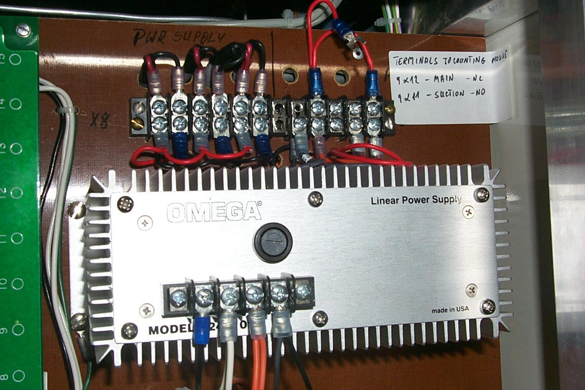
Rys.12 Electronics panel in the rack; connectors to be wired for remote pump down and turned off the system
There are two temporary cables 1 and 2, Fig.12 enabling running the cooling system without the remote stuff. They have to be removed when final wiring of the remote option occurs. The remote pump down button (normally open) should be connected to 5 and 4 terminals while the remote turn off button (normally closed) should be connected to 5 and 3 terminals. The remote control wire carry 24 V signals.
Emergency case means the main vacuum pump on/off cycle is shorter than 5 min. (to be decided)
2.10 Coolant removal from a number of cooling elements
The coolant can be removed from a number of cooling elements, while chilling the other elements. The octagon for instance, would then be emptied by closing V23 first and then somewhat opening V28 while observing that the water is flowing in the direction of the distributor. Valve V9 should then be closed, Fig.6, 7. The spectrometer arm can be emptied similarly. This method of water removal has the advantage of removing water with greater precision. However, it has the disadvantage that it slightly perturbs the operation of the remaining cooling circuits. Some of the air from the circuit that is being emptied gets through the distributor and interferes with the other elements.
The thermal shields can be emptied in different way. For instance, the outer upper thermal shield can be emptied of water by closing valve V6 and opening valve V13 for a short time. The water should be pushed towards the distributor while doing this. If the circuit is indeed being emptied, then valve V20 can be closed, ?? provided that the circuit is water tight. If the circuit has leaks in it, then the above operation can cause water to leak out of the system?? (it is Wojtek’s comment; I don’t understand it).
2.11 Roll out the detectors
If any detector has to be rolled out the magnet there is no necessity to disconnect its hoses. However, disconnection of the hoses is foreseen to make the roll out procedure easier. One must first remove the coolant from the circuitry concerned according to procedure described in 2.10. Then disconnect union, plug the return hose. To avoid incidental spillage of water closed also the manifold on the magnet with yellow cap, Fig. 13.
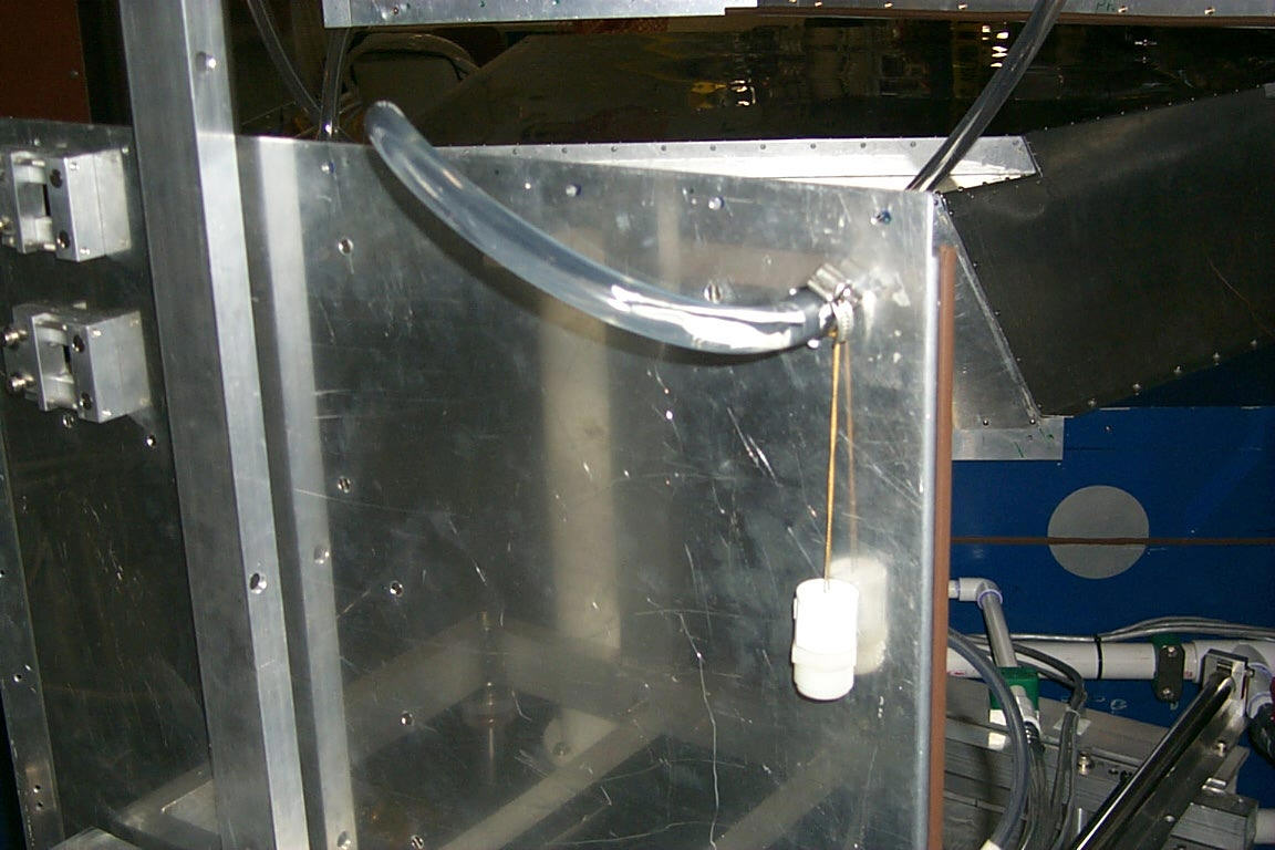
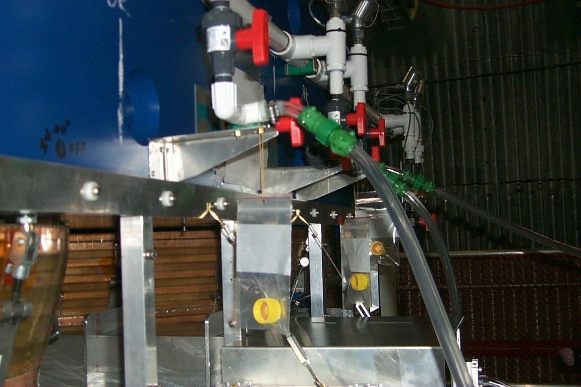
Fig.13 Disconnection of the detector return hoses
2.12 Chiller Turn-on
The chiller should be turned on according to its manufacturer instructions. We use a HX -150 model of NESLAB chillers, Fig.14. Capacity of the chiller reservoir is 8 gallons. To fill up the chiller circuitry prepare 10 gallons of specific liquid. NESLAB recommends using distilled water with Chloramine – T added against alga growth. Proportions recommended are given on the bottle label. The reservoir can be filled up from the top panel.
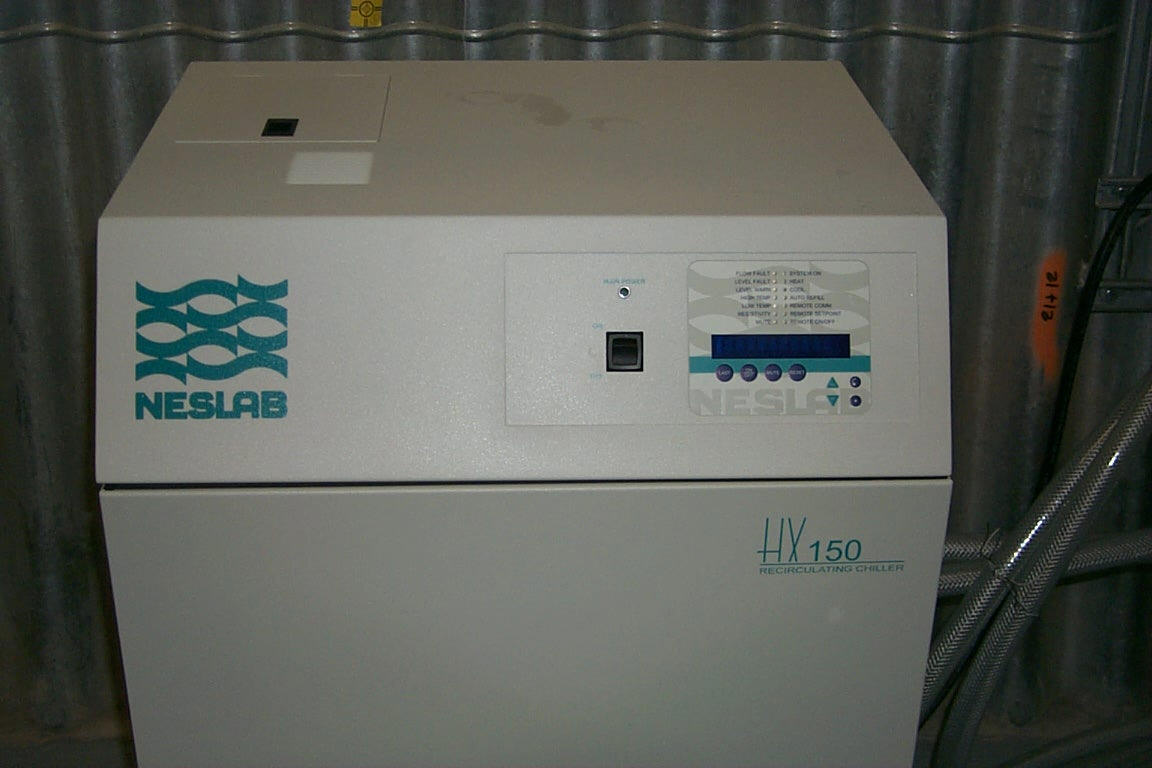
Fig. 14 Top and front panel of the chiller
The chiller is connected to the cooling system rack with two braid reinforced PVC hoses of 1" ID, Fig.15. The supply hose comes to a heat exchanger while the return one goes from an upper flow meter to the chiller. There should be about 10 Gpm flow in normal operation. The chiller has two valves allowing for its shut off. The valve on supply line is situated on a side panel while that one on return line is built in, Fig.16. The former allows for controlling water flow. The latter is a check valve.
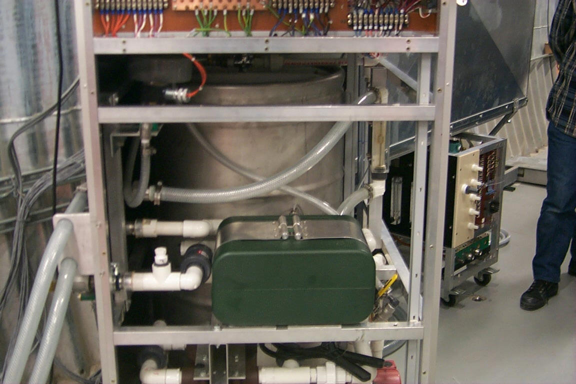
Fig.15 Chiller circuitry in the cooling system rack (cover sheets removed)
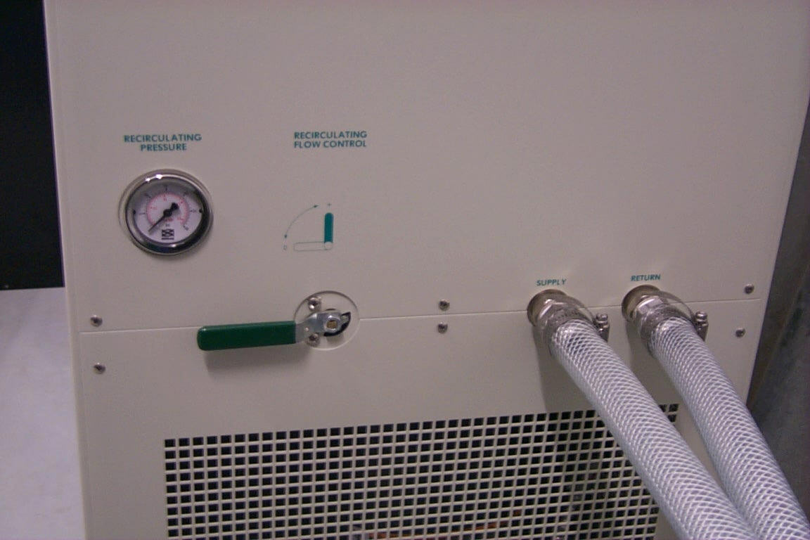
Fig.16 Side panel of the chiller
2.13 System Turn-off
Turn key MS to the left.
2.14 Maintenance
Check the coolant level in the tank and inspect the water filters periodically (once a month).. Also inspect the water tubes for algae build up at the lighted places. Check the floaters in the multi-channel flow indicator for blockage. Inspect the condensation area of the chiller and clean if necessary according to the chiller manual.
2.14.1 Coolant refill
It is recommended to refill the coolant before its level reaches minimum. Coolant refill is very easy while the system operated. A container with sufficient amount of the coolant and a hose of ½" ID is necessary. 1 cm at the coolant level indicator corresponds to about 0.7 gallon. Connect the hose to the valve V14, deep the hose in the coolant and open the valve. Close the valve when prepared coolant sucked, Fig.17. If coolant level reaches minimum the fill up procedure will have to be applied.
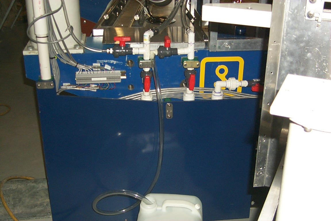
Fig.17 Coolant refill while the system ran
2.13.2 Inspection of water filters
To inspect the water filters turn off the system. Then, closed the valves V1, V2 and V5 in the rack. Use a plastic wrench to remove the filter body. If a cartridge is dirty replace it with the new one, Fig.18. Be prepared for water spillage.
Fig.18 Water filter cartridges replacement
3. Trouble shooting
3. Appendix