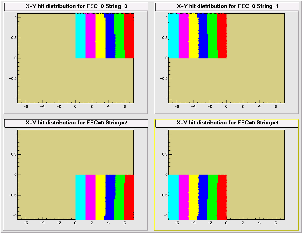
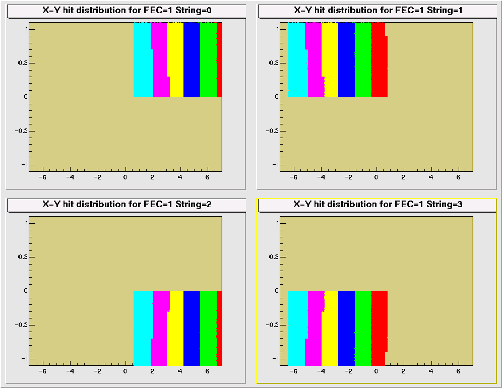
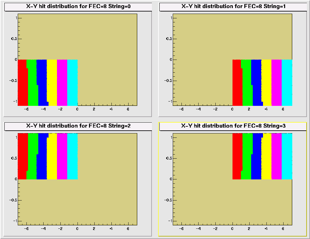
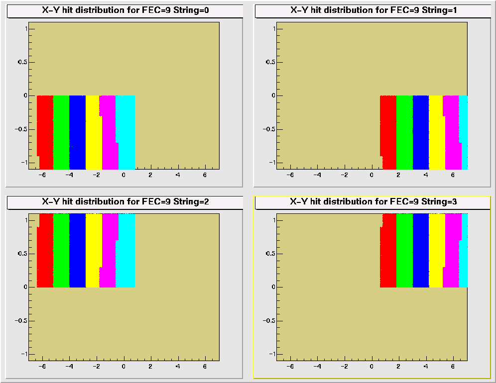
Positions of chips in strings 0,1,2,3
for FEC=0
Go to FEC0 chip positions
Go to FEC1 chip positions
Go to FEC8 chip positions
Go to FEC9 chip positions
Sometimes it is usefull to know what are the positions in space of pads connected to a particular channel. This information is neccessary to look for effects in raw signal processing associated with a particular geometrical configuration of the apparatus.
Below, there are four pictures showing positions of
pads connected to particular chips for FECs 0,1,8,9 and strings 0,1,2,3 used in the Test
Beam '98 experiment. Chip numbers are color labeled on these pictures. Chip 0 is seen in
red color, chip 1 as green, and so on up to chip no 5 colored blue.
Unfortunately also positions in Z direction change for a single FEC
value. Assignement between FEC/String nos and plane name is the following:
| FEC=0 | FEC=1 | FEC=8 | FEC=9 | |
| String=0 | NA00 | NC00 | NA01 | NC01 |
| String=1 | NA01 | NC01 | NA00 | NC00 |
| String=2 | NB00 | ND00 | NB01 | ND01 |
| String=3 | NB01 | ND01 | NB00 | ND00 |
Positions of chips in strings 0,1,2,3
|
|
Positions of chips in strings 0,1,2,3
|
 |
Positions of chips in strings 0,1,2,3
|
 |
Positions of chips in strings 0,1,2,3
|
 |
Written by Andrzej Olszewski on 04/06/99