When MTPC2 was tested at the laboratory, the maximum stable voltage on the anode wires was 1260 volts. Once installed on the Mid-rapidity platform, it was also stable with same voltage on the anode wires, and we were able to see pulses generated with a Ru source.
But later during the run, this TPC could not hold more than 1100 volts on the anodes. When the engineering run ended we investigated these problems. First we reproduced the trips without any change to the system. Later we connected the TPC to Bertan power supplies and found that, even if the field shaping and anode wires were at same potential, the power supplies would trip around 700 volts. And if we raised field shaper and anode wire voltages with independent power supplies, the field shaping wires would trip around 400 volts. This behavior led us to belive that this TPC had a broken wire and so we decided to move it back to the lab.
When we opened the TPC all wires on the readout plane were in place and there was no obvious connection between field shaping wires and anodes. There is a visible amount of soldering flux and some lint and dust on the pad plane.
We applied more than 1400 volts to the field shaper wires while the detector was filled of air. And the voltage stays stable without any sign currents flowing to ground.
Some of the tests on T1 at the lab. led us to a new set of voltage values for the readout plane. These new values came as a response to the fact that in the T1 readout (anode and field shaping wires between two ground planes) the sparks ocurred between anode and field shaper buses or wires.
The almost natural solution was to decrease the voltage gap between these two types of wires by placing the field shaping wires at higher positive potentials. When the shapers sit at higher potential the gain of the anodes is reduced. To compensate this loss, the voltage on the anode wires was raised to values close to 1600 volts. Further details of this work can be found in this report
It was not clear how good this solution is. At first sight it would appear that many drift lines would end up in the field shaping wires, only to be lost as signal because these wires do not amplify. But on the other hand, by looking at tracks left on T1 by a cosmic ray trigger, one can say that the readout is fully efficient because, whenever a clean track is recorded, it has a pulse in all instrumented pad rows.
It could be that the high field needed on the anodes compensated for the loss of electrons reaching them. Runing the TPC with too high gain on the anodes could make these detectors unstable.
In order to investigate further this new set of high voltage values we run a few Garfield simulations of the following system:
A plane of anode and field shaping wires (15 and 50 microns in diameter respectively) sitting at 2 millimiters of each other and two ground planes at 4.5 millimiters above and below the anode plane respectively
One of the first things we did was to look at the gain of the original set of high voltage values (anode: 1300, field shapers 0 volts) and new settings where the field shapers sit at higher voltage. From previous experience on wire chambers, we know that an electric field of some 200000 volt/cm at the surface of the anodes will produce a gain of 10000. In the he following table we use the value of the electric field at the surface of the anodes to compare these different configurations.
| Setting | Anode voltage | Field shaper voltage | E field at anode surface [volt/cm] |
| A | 1300 | 0 | 255000 |
| B | 1300 | 200 | 239000 |
| C | 1650 | 0 | 320000 |
| D | 1650 | 750 | 262400 |
From this table one can see that the setting D will produce the same gain as the setting A. And together with the results obtained with T1 in the cosmic ray trigger one can conclude that because the pulses recorded are comparable to those seen in MTPC1, there are no big losses to the field shaping wires.
In order to have a better understanding of setting D we display the equipotentials for setting A and D.
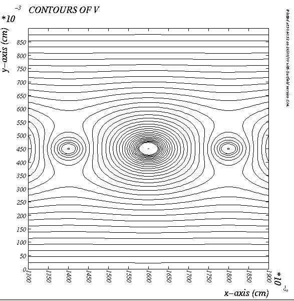
In this figure the contours correspond to values ranging from 0 to 640 volts in 32 steps of 20 volt.
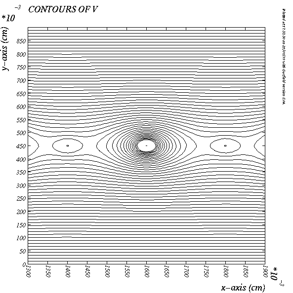
For this setting the contours correspond to values ranging from 0 to 960 volts in 48 steps of 20 volt.
In both settings electrons drifting to the anode pass through a region of constant or slowly changing electric field and then enter a second region with cylindrical symmetry centered on the anode. Within this region the potential has a logaritmic dependance that produces the high electric field that amplify the signal.
One difference stands out from these plots; by raising the field shaper voltage we have reduced the thickness of the log r region. If we were dealing with a traditional wire chamber this set of voltages would not be acceptable because a charged particle would leave ionization in the linear and logaritmic regions. Each one of these regions would have different drift modes and that would affect adversely the time resolution of the counter. In our TPCs, the ionization is deposited in the drift volume and the readout system is practically an independent part that collects and amplifies the electrons that have drifted into its volume. The linear region becomes an extension to the drift volume.
Eventhough one would not design a readout system with voltages as those of setting D, it appears as a possible choice for our TPCs once we exhaust all efforts to use them in setting A. Setting D doesn't have big gradiants that would make it unstable (T1 ran for weeks without tripping). We still have to quantify the loss of electrons to the field shapers, and we should also pay attention to the way positive ions produced in the avalanche drift to the ground planes. The shape of the signal is determined by the work done by the power supplies to drift these ions. One concern for the new settings is that the regions of constant electric field may extend the presence of positive charges in the system and create a space charge problem. The following figure displays the electric field along a vertical line passing through one of the anodes.
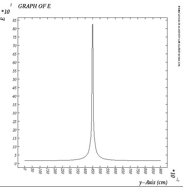
With this figure we want to illustrate the two regions of field refered above; close to the anode the field varies as 1/r, and some half a millimeter away from it the field is basically constant or slowly changing from 5000 to 1800 volt/cm.
The magnitude of E closer to the cathode planes is higher for setting D making it a prefered set of voltage values because it produces an output pulse that decays faster in time.
To have an idea about what fraction of the electrons will drift to the field shaper wires we will study the horizontal component of the electric field Ex along a horizontal line that passes through the center of the wires.
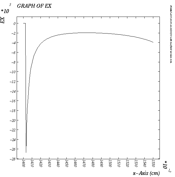
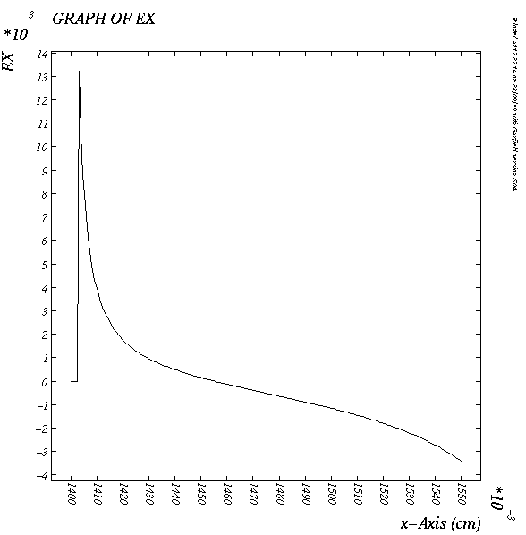
For setting D Ex changes sign half a millimeter away from the field shaping wire. We conclude then that 1/4 of the cell will not amplify the signal.
This work is being done by: Ch. Chasman, and R. Debbe