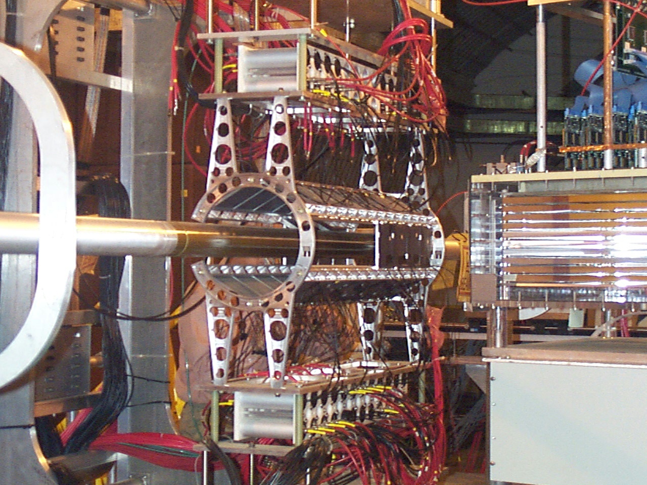
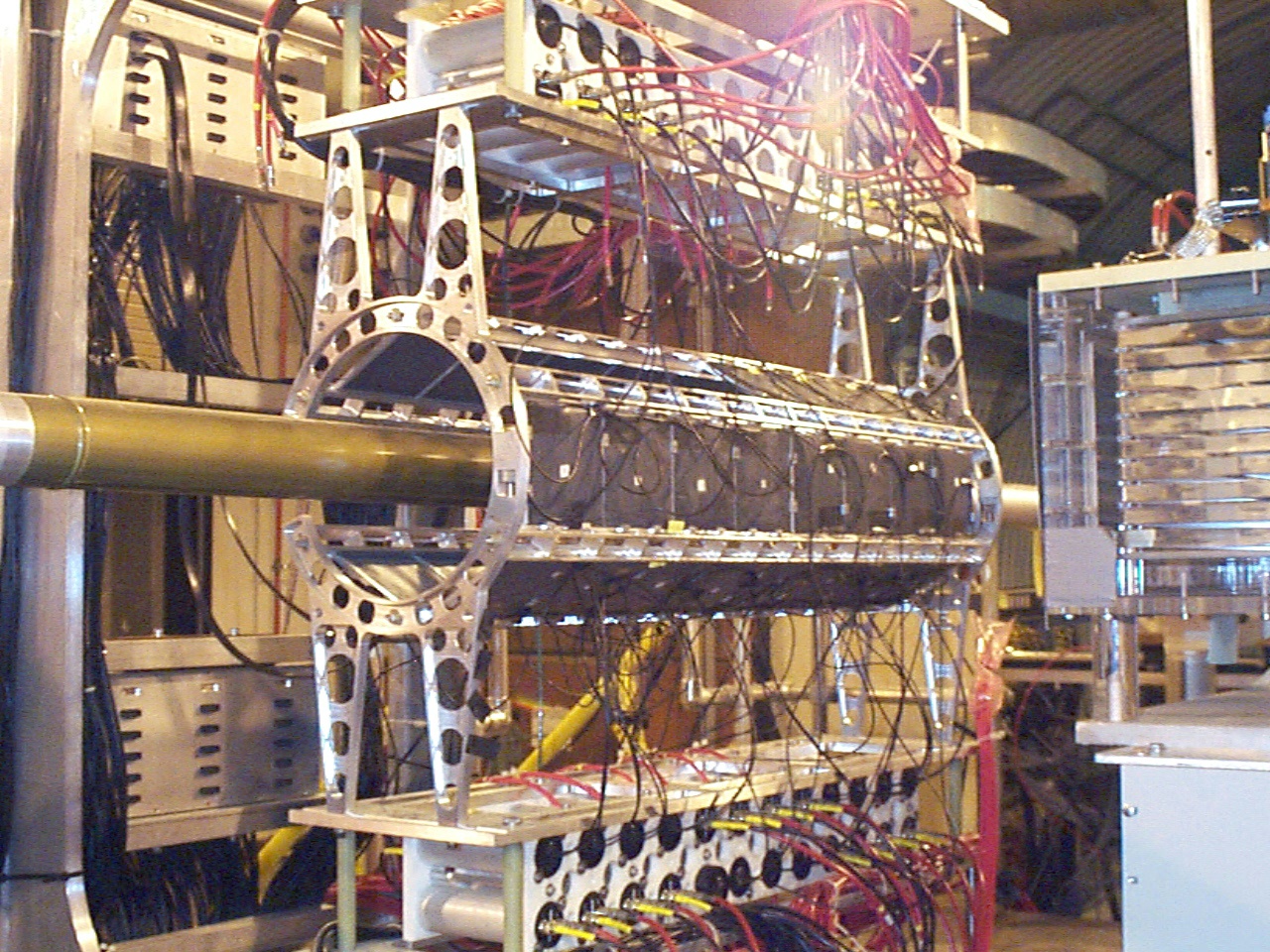
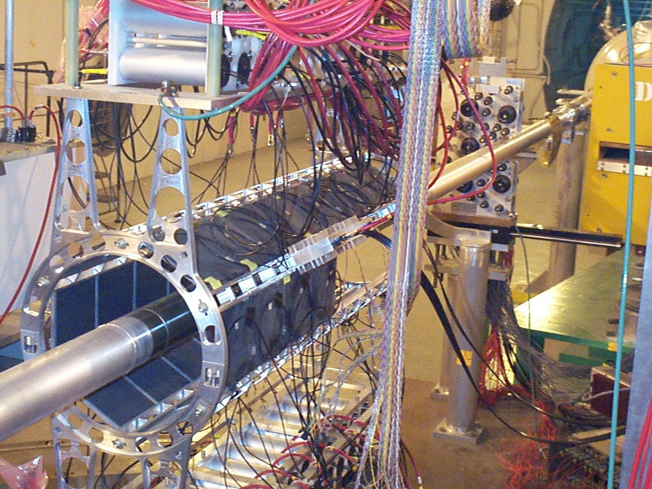
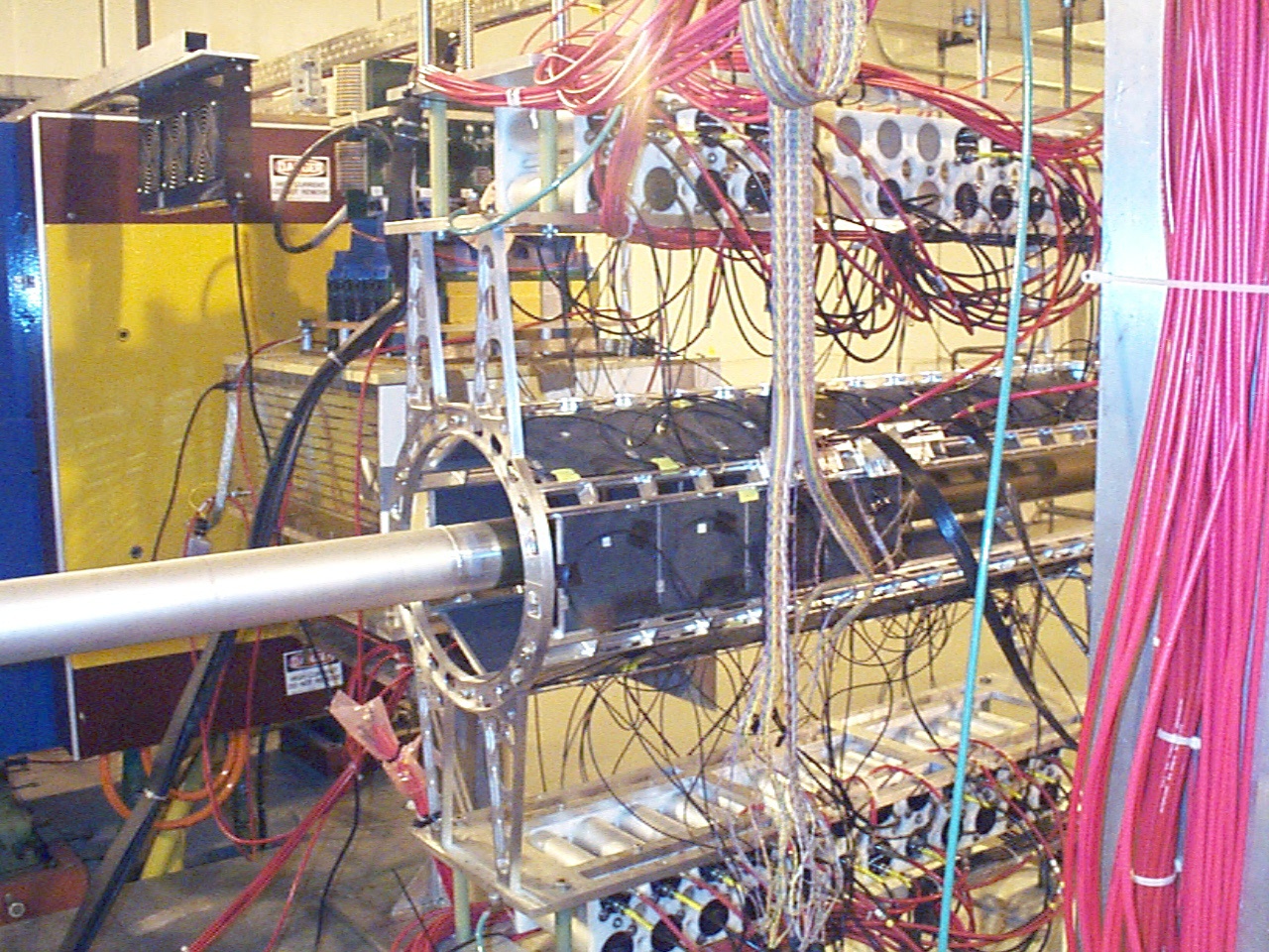
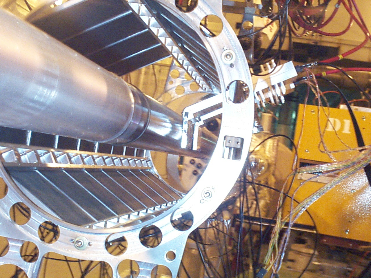
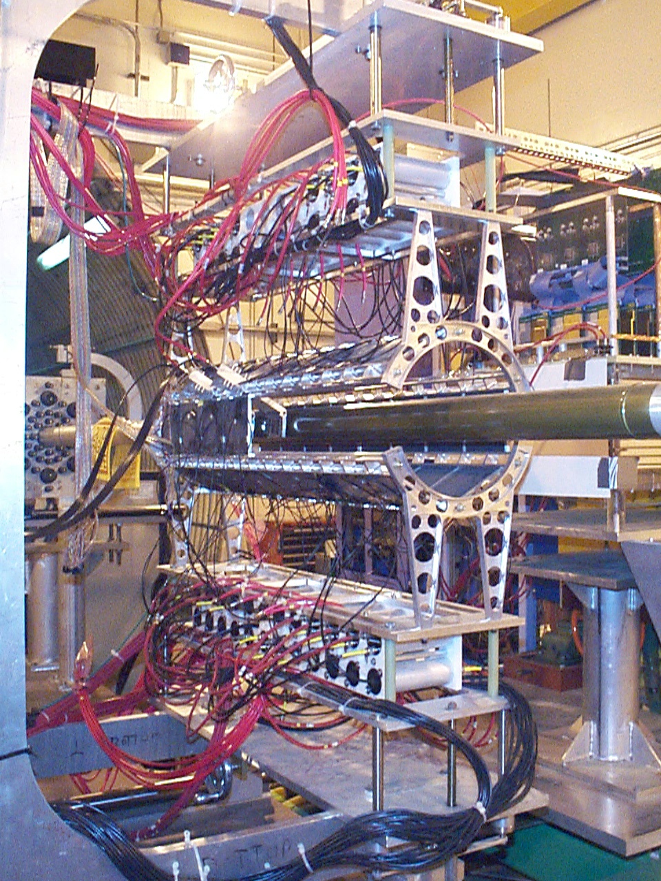
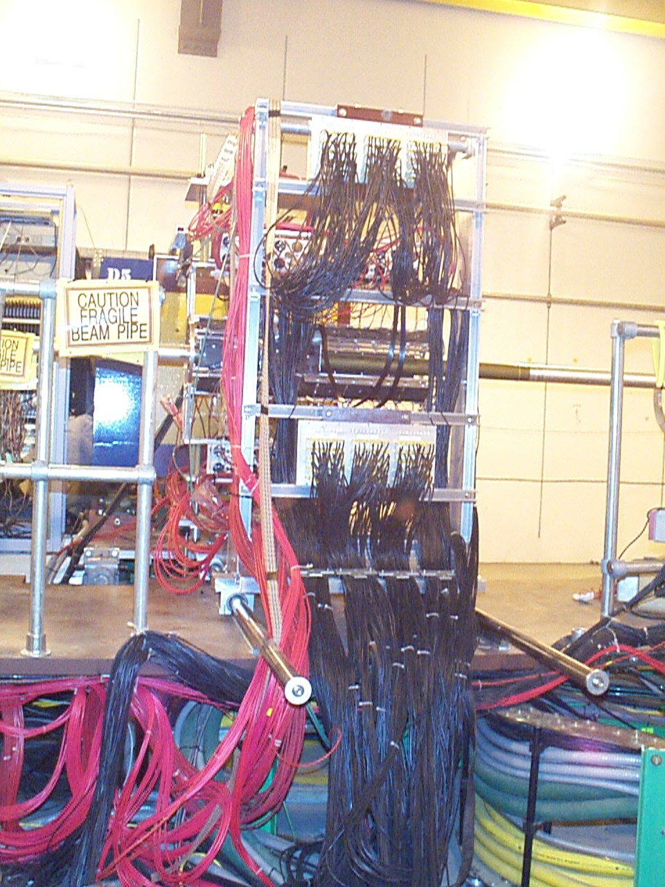
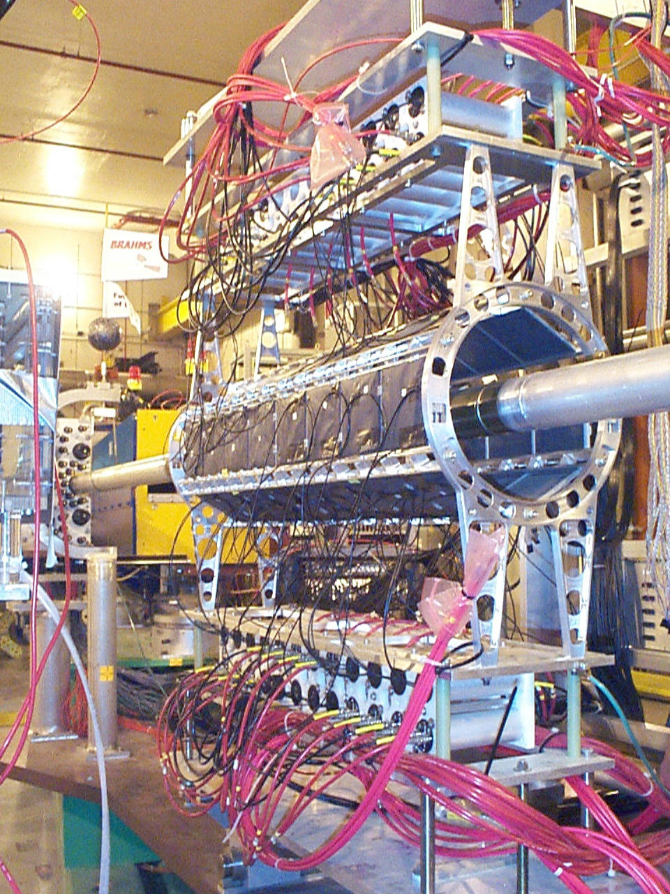
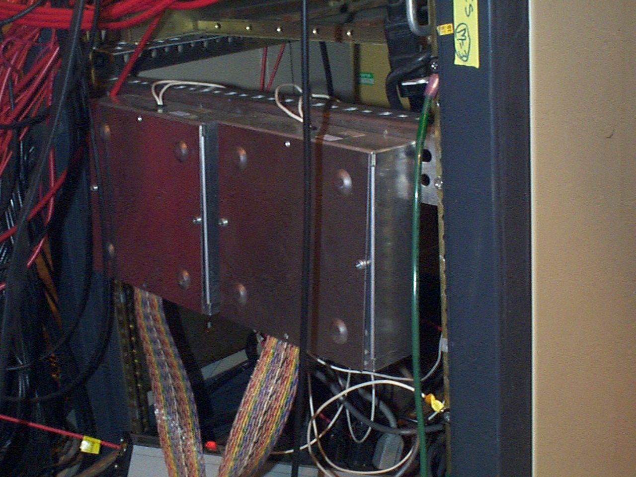
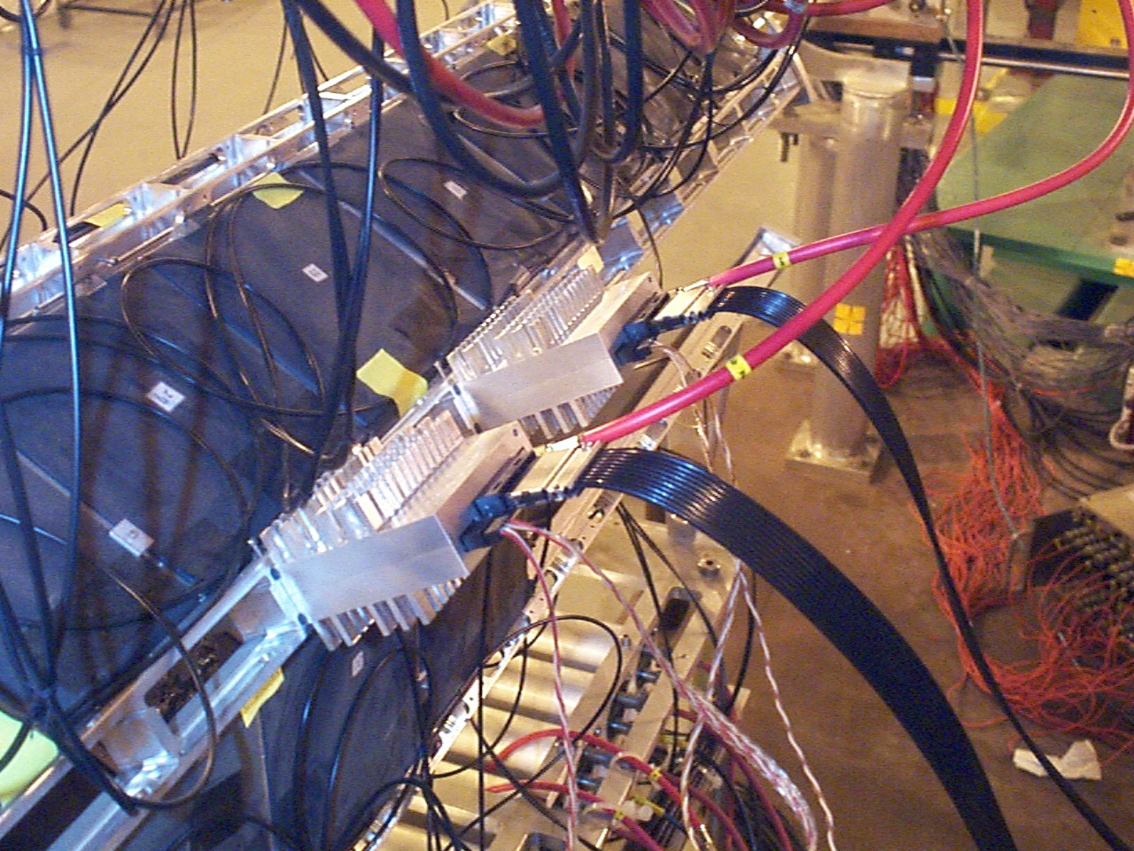
The following is a general diagram of cable layout
of silicon strip detectors.
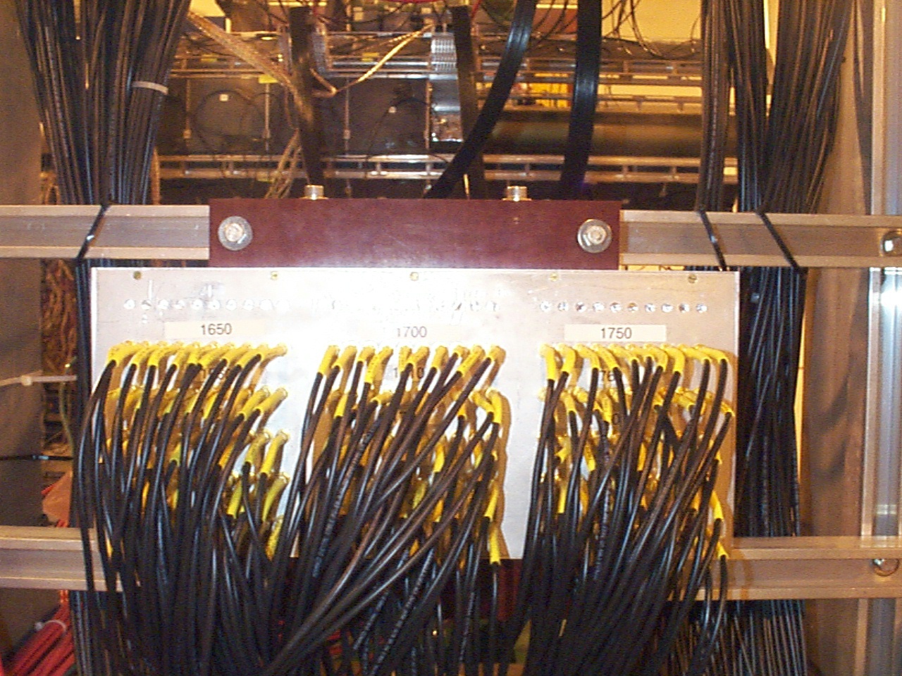
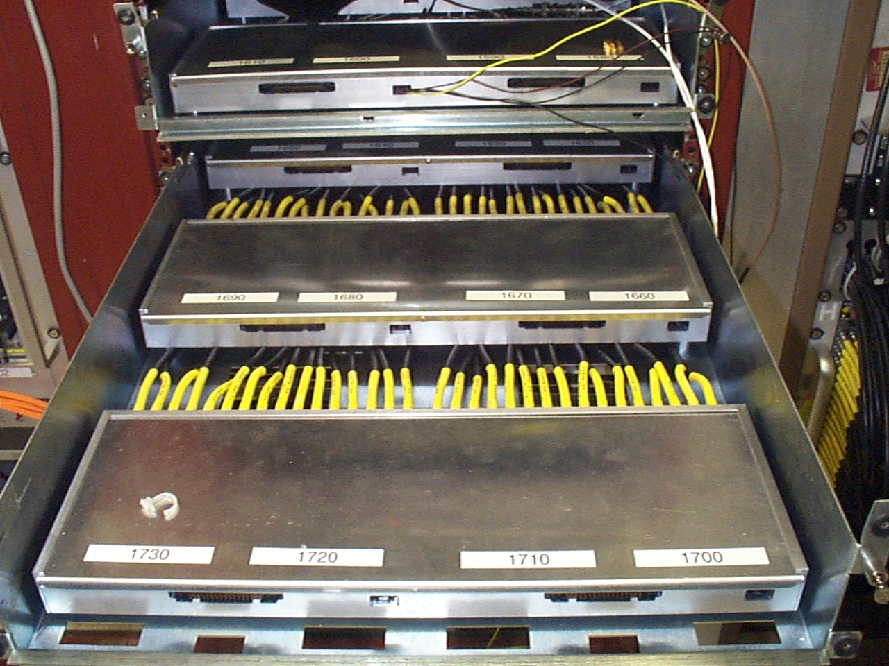
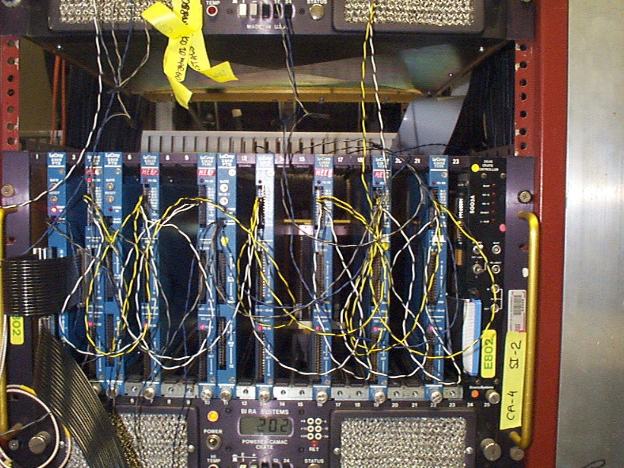
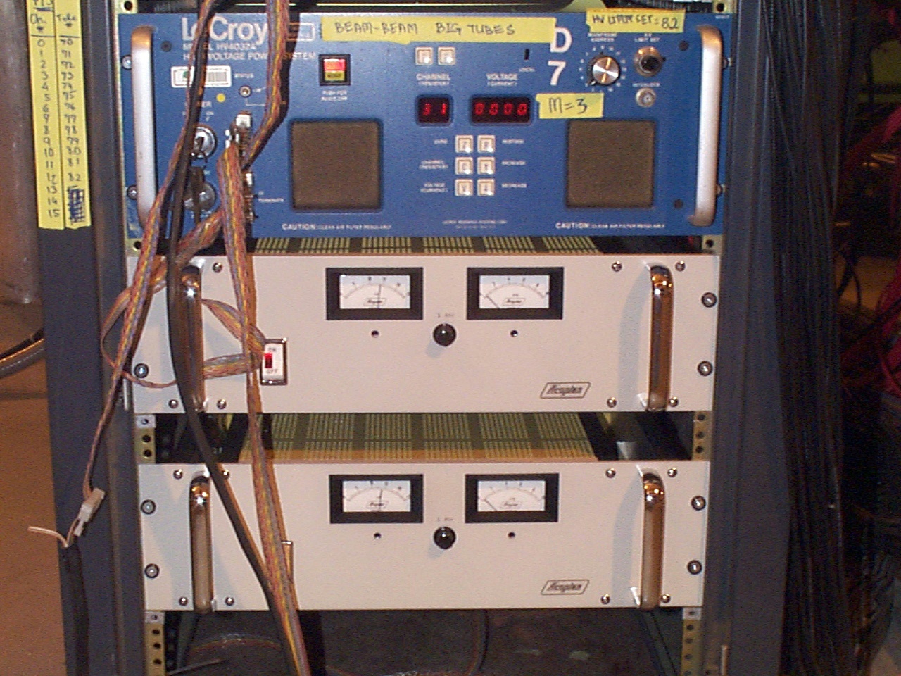
This is the table for detail cable connections.
| Silicon Location | IR Patch | Signal Cable | Attenuator | PTQ | FERA | HV | |
| 1-1 | |||||||
| 1-2 | |||||||
| 1-3 | |||||||
| 1-4 | |||||||
| 1-5 | |||||||
| 1-6 | |||||||
| 2-1 | |||||||
| 2-2 | |||||||
| 2-3 | |||||||
| 2-4 | |||||||
| 2-5 | |||||||
| 2-6 | |||||||
| 3-1 | 1610 | 1610-1619 | 1610 | 7(9-16 ch) | 7(9-16 ch) | 180-2 | |
| 3-2 | |||||||
| 3-3 | 1600 | 1600-1609 | 1600 | 7(1-8 ch) | 7(1-8 ch) | 180-1 | |
| 3-4 | |||||||
| 3-5 | |||||||
| 3-6 | |||||||
| 4-1 | |||||||
| 4-2 | |||||||
| 4-3 | |||||||
| 4-4 | |||||||
| 4-5 | |||||||
| 4-6 | |||||||
| 5-1 | |||||||
| 5-2 | |||||||
| 5-3 | |||||||
| 5-4 | |||||||
| 5-5 | |||||||
| 5-6 | |||||||
| 6-1 | |||||||
| 6-2 | |||||||
| 6-3 | |||||||
| 6-4 | |||||||
| 6-5 | |||||||
| 6-6 |